-
추가:: 둥관 헝주탕 로드 8호 빌딩 2, 동관
-
전화: 전화 +86 135 4224 3751

Graphene Thermal Pad for 1.6T OSFP High-Speed Optical Module
As AI computing power accelerates rapidly, optical modules—serving as the core medium for high-speed data center interconnects—are evolving quickly toward higher integration, miniaturization, and higher data rates. With the increasingly widespread deployment of 800G technology, the large-scale commercialization of 1.6T optical modules is also just around the corner.
At the same time, as bandwidth upgrades continue and the power consumption of core components rises, effective thermal management is no longer a secondary consideration; rather, it has become a fundamental requirement for system stability, reliability, and consistent performance.
In this article, drawing on a real-world project case study, we highlight the practical application of Sheen’s GSF90-03 thermal pad in 1.6T OSFP high-speed optical modules.
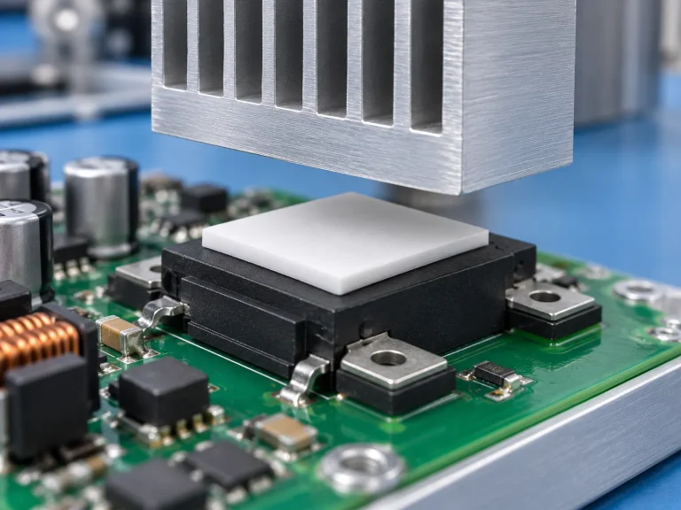
Because 1.6T OSFP modules run hotter in cramped spaces, a Graphene Thermal Pad for 1.6T OSFP High-Speed Optical Modules can move concentrated heat through a thin interface. Hotspots don’t care about marketing; thermal impedance, fit, and reliability matter most.
For buyers, the plot thickens: compare graphene with compressible silicone, then verify insulation, die-cutting, adhesives, compliance, and consistency.
Graphene Thermal Pad for 1.6T OSFP High-Speed Optical Module
- Delivers exceptional thermal conductivity to spread heat from power-dense modules, stabilizing operating temperatures.
- Offers ultra-low thermal impedance for efficient heat transfer between transceiver housing and heatsinks.
- Maintains thin, flexible profiles to conform within cramped OSFP interfaces without excessive compression.
- Ensures long-term reliability with thermal-aging resistance, RoHS/REACH compliance, flame-retardant and halogen-free options.
Graphene Vs. Silicone For Module Cooling
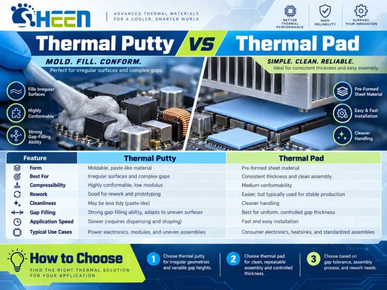
Cooling a 1.6T optical link gets tricky when high power meets very little space. The Graphene Thermal Pad for 1.6T OSFP High-Speed Optical Module targets faster heat transfer, while silicone favors softness and insulation. Picking the right contact layer can keep temperatures under control without making assembly a headache.
Graphene Thermal Pad
Graphene stands out when low 열 저항 matters inside the compact OSFP form factor. A Graphene Thermal Pad for 1.6T OSFP High-Speed Optical Module uses a thin nanomaterial path to move concentrated heat toward the heatsink.
- Thermal performance
- 높음 열 전도성 supports rapid 열 방출 from a power-dense high-speed optical module.
- The thin interface material can reduce the distance heat must travel, which is a big deal when space gets tight.
- Design fit
- A Graphene Thermal Pad for 1.6T OSFP High-Speed Optical Module works best when mating surfaces provide controlled, fairly even contact.
- Sheen Materials can support thermal-pad choices for 1.6T OSFP designs where conduction efficiency and compact installation both count.
In short, a graphene thermal pad suits designers chasing a strong thermal path without piling on interface thickness.
Silicone Thermal Pad
Silicone takes a different route. This flexible elastomer material acts as a 갭 필러, conforming to height differences that may otherwise leave unwanted air pockets.
- For uneven surfaces, its 압축성 helps maintain physical contact with the module and heatsink.
- For electrical protection, useful insulation performance can separate conductive parts while still supporting 열 관리.
- For changing operating conditions, good temperature stability helps the pad retain practical performance over repeated heating cycles.
The trade-off is conduction efficiency: conventional silicone often transfers heat less effectively than graphene. So, when specifying a Graphene Thermal Pad for 1.6T OSFP High-Speed Optical Module against a silicone thermal pad, engineers need to weigh surface fit against heat flow. Sheen Materials offers options for both priorities, making material selection less of a guessing game.
3 Reasons Graphene Thermal Pad Excels In OSFP
Graphene Thermal Pad for 1.6T OSFP High-Speed Optical Module applications face serious heat in tightly packed switch hardware. A well-matched pad moves that heat toward the cooling assembly while maintaining electrical separation. Sheen Materials offers thermal interface options designed around these demanding OSFP operating conditions.
Superior Thermal Conductivity for 1.6T OSFP Optical Modules
Graphene Thermal Pad for 1.6T OSFP High-Speed Optical Module designs benefit from high 열 전도성, since a power-dense 1.6T OSFP can create concentrated hot spots.
- Heat spreading
- A thin graphene pad carries heat away from the optical module surface.
- Better 열 방출 helps limit local temperature rise.
- Cooling support
- The pad links the high-speed transceiver with nearby cooling hardware.
- Effective thermal management can support steadier operation under heavy traffic.
Ultra-Low Thermal Impedance in High-Speed Transceivers
낮음 열 임피던스 matters because conductivity alone does not tell the whole story.
- At the interface: A conformable graphene material can reduce 접촉 저항 across small surface gaps.
- Across the pad: Lower interface resistance supports efficient 열 전달 from the high-speed transceiver into its heat sink.
- In service: Good fit and controlled thickness help maintain predictable 열 성능.
That makes Graphene Thermal Pad for 1.6T OSFP High-Speed Optical Module integration practical when every degree counts.
Outstanding Electrical Insulating Property
전기 절연 adds another layer of protection where conductive parts sit close together.
- Isolation property: An insulating graphene pad can separate electrical surfaces while still conducting heat.
- Dielectric strength: The specified rating should match voltage, pad thickness, and OSFP design needs.
- Electronic safety: Proper insulation supports short-circuit protection and can help avoid unwanted electrical paths that may affect signal integrity.
Sheen Materials can match an insulating graphene thermal interface pad to mechanical, thermal, and dielectric targets rather than treating insulation as a one-size-fits-all spec.
Overheating Modules? Use Graphene Thermal Pad Now
A Graphene Thermal Pad for 1.6T OSFP High-Speed Optical Module gives concentrated heat a wider path to escape. In tightly packed networking gear, that matters a lot: controlled contact, slim material, accurate cutting, and stable performance help keep demanding optical links running cooler.
Why Graphene Pads Combat Thermal Runaway in Networking Hardware
A graphene thermal pad spreads heat from a high-speed optical module before a local hotspot pushes temperatures upward.
- Heat path
- High in-plane 열 전도성 moves energy toward a larger cooling area.
- Better 열 방출 supports steadier temperature control in dense networking hardware.
- Hotspot management
- Lower peak temperature can reduce conditions that contribute to thermal runaway.
- A Graphene Thermal Pad for 1.6T OSFP High-Speed Optical Module can connect a hot module surface with the intended cooling structure.
| Operating case | Module load | Hotspot risk | Thermal goal |
|---|---|---|---|
| Moderate traffic | 50% | Medium | <85°C |
| Heavy traffic | 80% | 높음 | <85°C |
| Full traffic | 100% | Highest | <85°C |
These values illustrate design targets, not guaranteed device results.
Achieving Thin Profiles: Thickness and Flexibility Advantages
A thin profile suits the tight space constraint around an OSFP cage. That small detail can save a lot of assembly hassle.
- 제어 두께 preserves the intended module form factor.
- 재료 유연성 그리고 mechanical compliance help bridge minor height tolerances without heavy clamping pressure.
- A suitable bending radius lets a graphene pad follow the contact geometry while avoiding sharp folds.
The result is a slimmer thermal path for 1.6T OSFP hardware.
Precision Slitting & Surface Treatment for Perfect Module Contact
Good heat spreading still depends on close module contact.
- Manufacturing control
- Precision slitting 그리고 다이 커팅 set clean dimensions for OSFP parts.
- 제어 flatness reduces gaps that can trap insulating air.
- Interface preparation
- Surface treatment can improve fit and handling.
- Lower interface resistance helps the 열 인터페이스 재료 transfer heat into the cooling assembly.
Adhesive backing and release liners also make placement less fiddly during production.
Compliance and Reliability: Thermal Aging Resistance & RoHS Standard
Long service life calls for stable material properties, not just good day-one numbers. Thermal aging testing checks 장기적인 안정성 그리고 내열성 after extended temperature exposure.
For practical qualification, buyers can also review the RoHS standard, environmental compliance, and controls on each hazardous substance. Flame-retardant and halogen-free choices may suit specific equipment specifications, while documented 신뢰성 data helps engineers compare graphene thermal pad options for demanding network hardware.
Sheen Materials 1.6T OSFP Thermal Interface Material Project
There are currently two mainstream thermal designs for 1.6T OSFP high-speed optical modules:
Project Overview
RHS: Riding Heat Sink
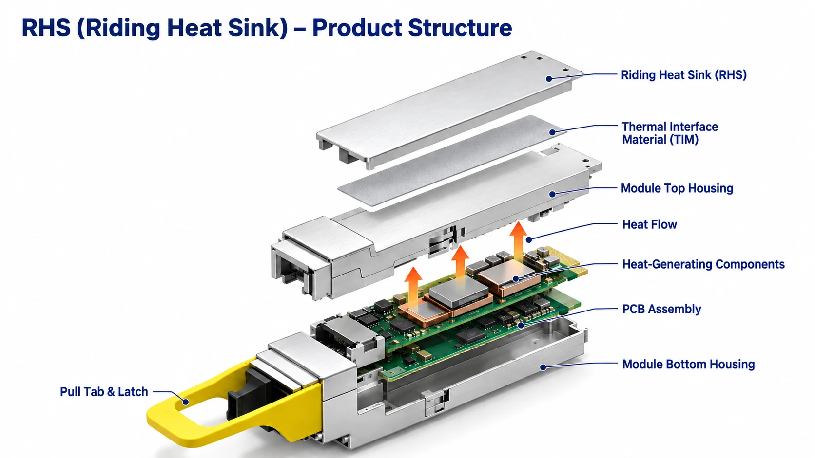
IHS: Integrated Heat Sink
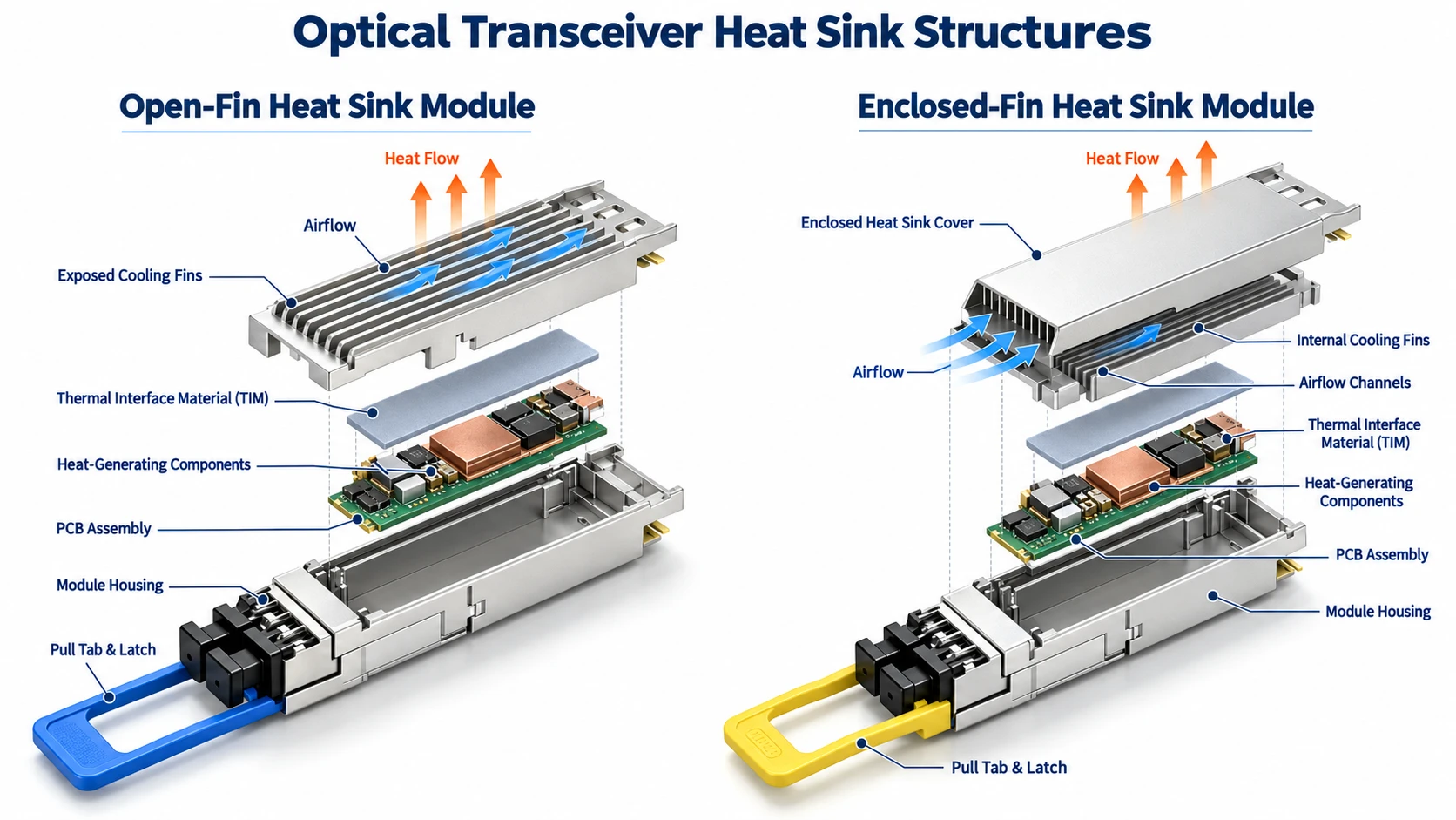
Primary heat source of the 1.6T OSFP: The DSP (Digital Signal Processing) chip, utilizing a 3nm process and bare-die packaging; typical power consumption is approximately 17W, and the die size is roughly 6mm x 5mm.
Heat Transfer Path: DSP → Thermal interface material → Heat sink
- DSP Chips: Broadcom and Marvell offer the mainstream solutions in the industry.
- Thermal Interface Materials: Currently, the technology is primarily divided into two main categories—post-curing thermal gels and graphene thermal pads.
- Heat Sink: Mainstream industry thermal management solutions encompass various configurations; this project employs an architecture featuring an aluminum alloy housing with CNC-machined raised mounting pads, combined with a saddle-mount heat sink and air cooling.
- Aluminum alloy housing with CNC-machined raised features.
- Extruded copper air duct with CNC-machined raised features.
- Integrated vapor chamber (VC) heatsink.
- Next-generation option: Molded copper-diamond composite housing.
- Indirect liquid cooling: Refrigerant flow channels integrated into the housing.
4. Assembly clearance: The design clearance between the thermal interface material and the CNC-machined boss on the housing is approximately 0.3 mm.
Competitor Solutions and Project Pain Points
During the preliminary stage of the thermal management solution design, the user evaluated mainstream post-curing thermal gel products in the industry:
- Competitor A: a single-component, post-curing thermal gel with a thermal conductivity of 12 W/m·K;
- Competitor B: a two-component thermal gel with a thermal conductivity of 14.5 W/m·K.
Following accelerated curing at 85°C for two hours, debonding was observed at the interfaces between the thermal gel and both the bare die and the housing boss. This resulted in a significant increase in interfacial thermal resistance, causing the DSP chip’s temperature rise to exceed limits and failing to meet long-term product reliability requirements.
Given that this failure recurred in 100% of cases across multiple iterative tests, the customer decided to abandon the thermal gel curing approach in favor of a graphene thermal pad solution, while also specifying clear technical requirements.
Technical Specification Requirements:
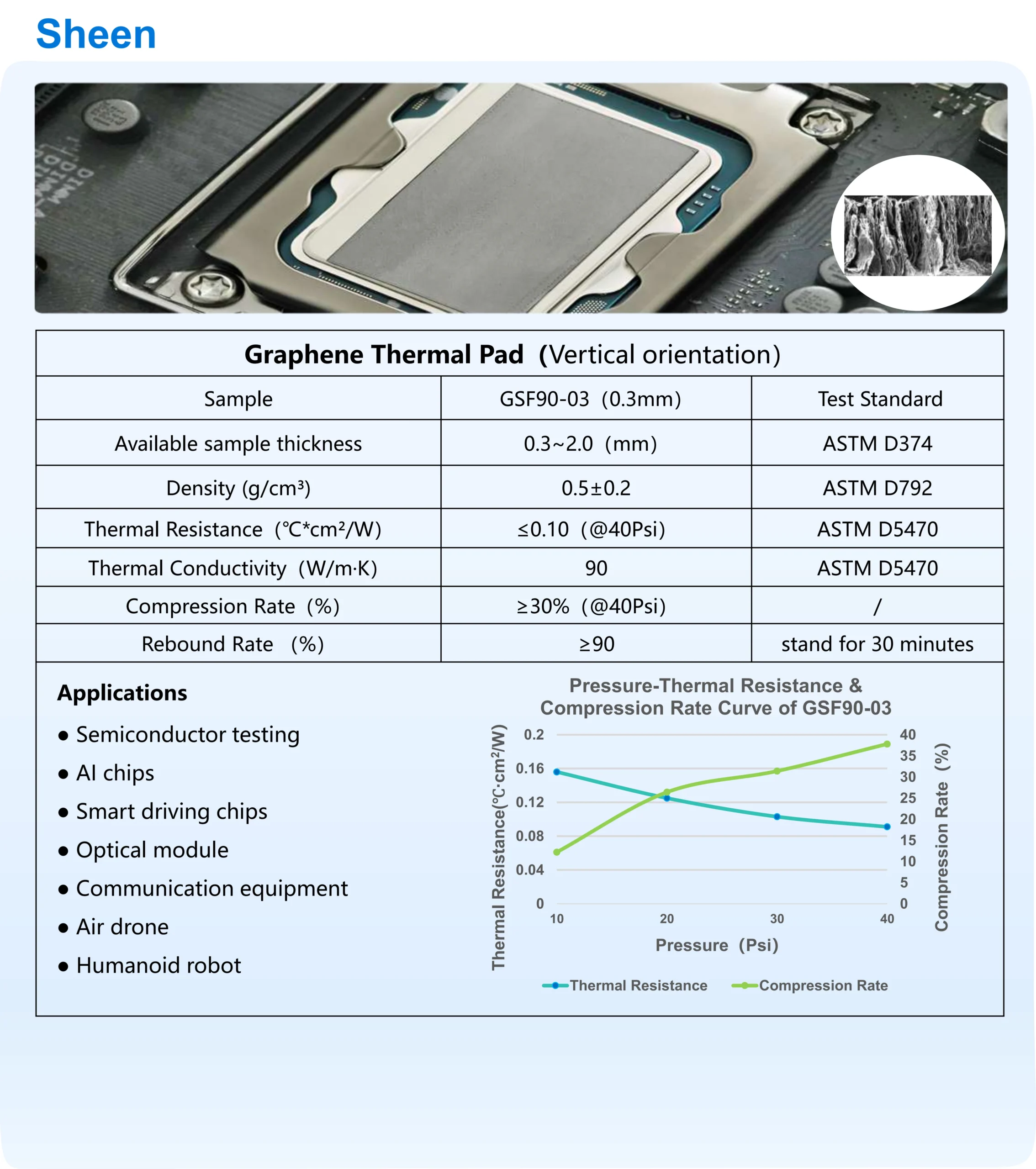
- Initial gasket thickness: 0.3 mm; interfacial thermal resistance < 0.1°C·cm²/W at 40% compression.
- Compressive stress < 40 psi at 40% compression.
- Rebound rate ≥ 90%.
- Appearance: No powder shedding; free from significant cracks, indentations, or pits.
- Edge protection: Side edge sealing/coating required.
- Single-sided dispensing required; dispensing location customizable.
Thermal design target: DSP chip junction temperature Tj < 85°C
Sheen Materials Solutions
Product Recommendation: GSF90-03
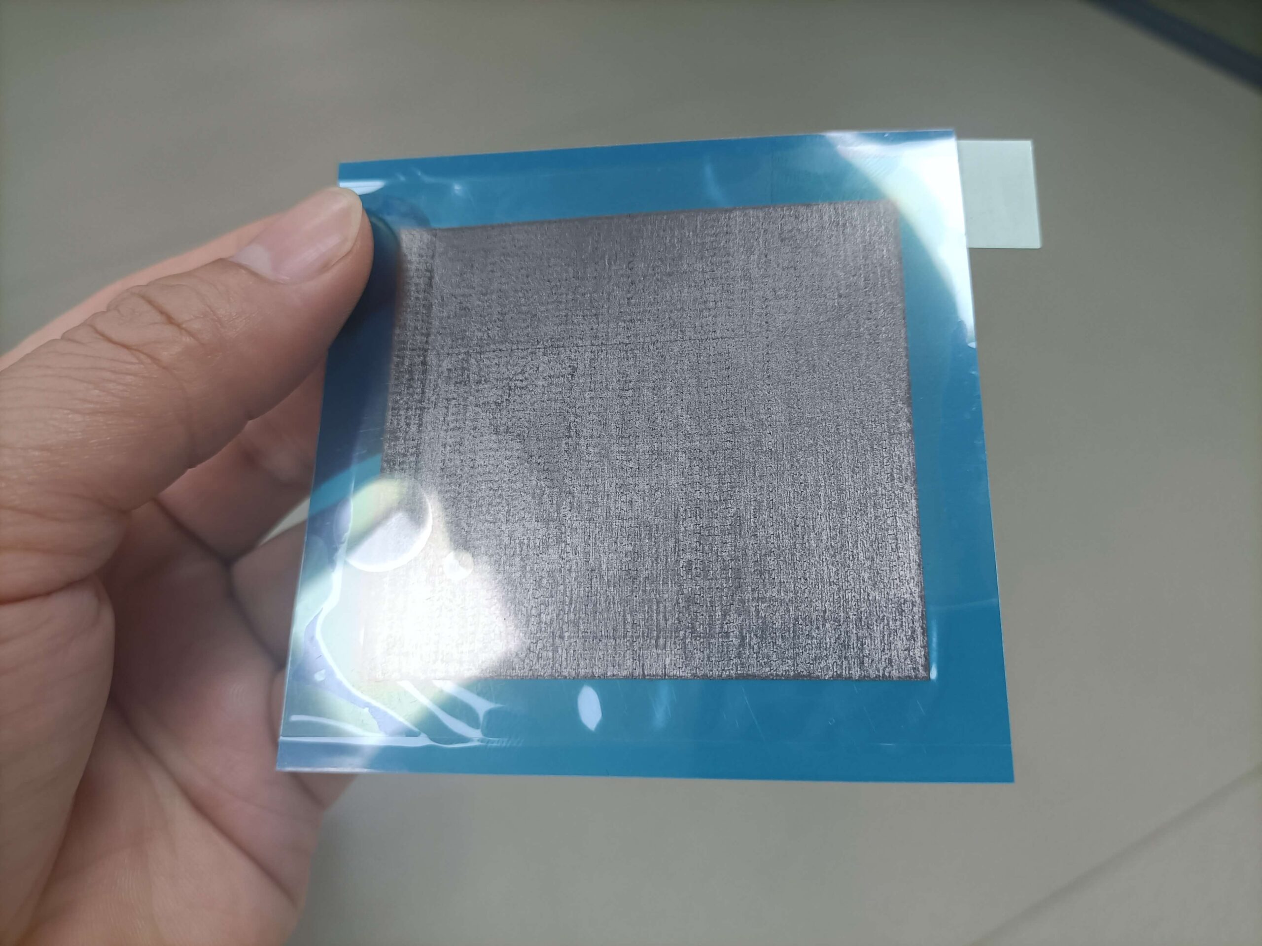
Protection and Structural Design:
① Surface-mount capacitors are densely arranged around the DSP chip, with a clearance of only 0.5 mm to 1.0 mm between the chip edge and the components; loose graphene debris poses a significant risk of causing capacitor short circuits.
② The project employs a dual-protection strategy: damming adhesive is applied at the base, combined with a foam frame to provide a physical barrier; simultaneously, positioning grooves are incorporated into the inner surface of the metal housing, paired with custom positioning tooling to ensure assembly alignment accuracy.
Production Line Compatibility:
Designed for automated vacuum suction cup operations during mass production, enhancing assembly efficiency and consistency to meet large-scale manufacturing requirements.
Actual performance results
Test conditions: ambient temperature of 45°C and effective airflow of approximately 15 CFM. The measured junction temperature of the DSP chip was approximately 76°C, outperforming the design target of Tj < 85°C; the thermal performance meets the requirements for the entire unit.