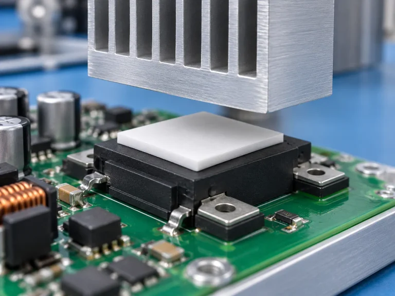
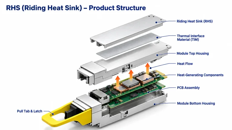
-
ADD: Building 2, No. 8 Hengzhutang Road, Dongguan
-
Phone: +86 135 4224 3751

Silicone vs. Non-Silicone: A Silicone-Free Thermal Pad Selection Guide
Silicone-free thermal pad selection guide cuts straight to the pain: overheating chips, messy residue, and returns stacking up when silicone quietly breaks down under pressure.
Silicone pads feel safe, but in dense builds they creep, outgas, and quietly drive up real long-term costs.
According to Sheen Materials engineers in 2025 briefs, non-silicone pads provide stability and reduce contamination risks in high-cycle applications.
Key Highlights of the Silicone-free Thermal Pad Selection Guide
→ Embrace Halogen-Free Elastomerics: Meet REACH and RoHS while ensuring strong thermal conductivity in power modules and LED arrays.
→ Enhance Long-Term Reliability: Prevent outgassing, pump-out, and voids under thermal cycling in CPUs, GPUs, and IGBTs.
→ Compare Material Options: Choose between gap fillers, phase-change materials, graphite sheets, and polymer composites for optimal heat spread and dielectric strength.
→ Follow a 5-Step Selection Process: Assess thermal conductivity, dielectric properties, shore hardness, manufacturing methods, and UL/environmental certifications.
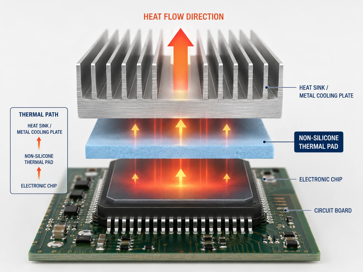
Why Choose Silicone-Free Thermal Pads?
Choosing the right interface material can feel tricky, but this Silicone-free thermal pad selection guide keeps it simple, practical, and grounded in real-world engineering needs. If you’re comparing options for CPUs, GPUs, LEDs, or power modules, this silicone-free thermal pad guide helps break things down clearly.
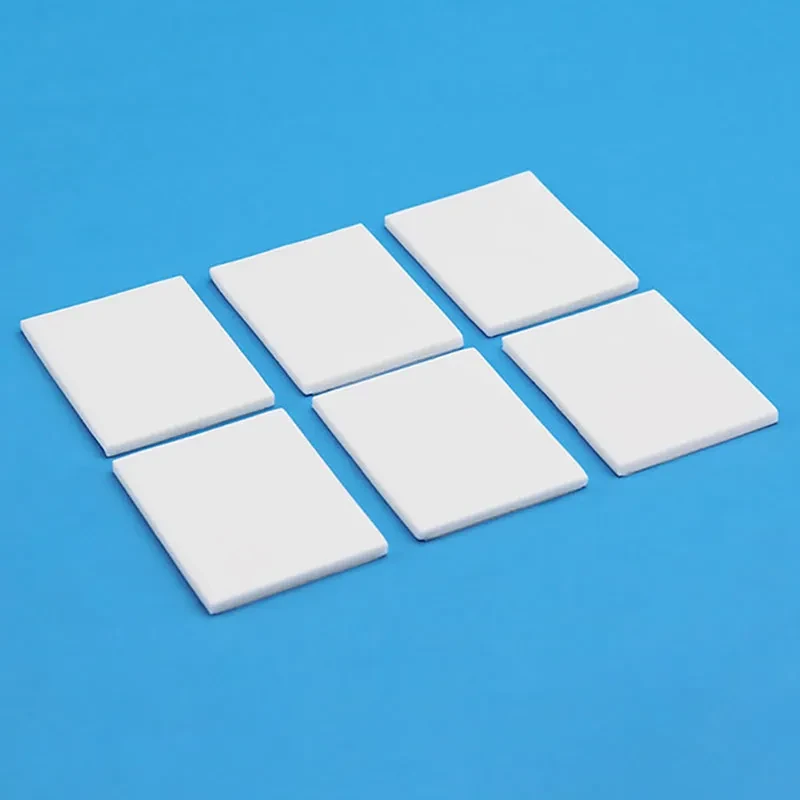
Halogen-Free Elastomeric Pads for Greener Electronics
A smart Silicone-free thermal pad selection guide always starts with environmental impact. Modern electronics demand eco-friendly, non-toxic, and sustainable materials that align with global compliance goals.
- Core Environmental Advantages
- Reduced hazardous halogen compounds
- Lower toxic emissions during disposal
- Improved manufacturing safety
- Regulatory Alignment
- REACH-focused material screening
- Cleaner supply-chain documentation
- Verified environmental standards
- Application-Level Benefits
- Stable thermal interface in LED arrays
- Reliable components for EV power systems
From raw material sourcing to end-of-life recycling, halogen-free elastomeric pads reduce environmental strain while maintaining consistent conductivity. For brands targeting greener certification, Sheen Materials integrates material traceability directly into production workflows.
If you’re reviewing a silicone-free TIM selection guide for energy-conscious design, this is where the conversation usually starts: cleaner chemistry, fewer regulatory headaches, and better long-term sustainability metrics.
Boosted Long-Term Reliability without Silicone
The heart of any Silicone-free thermal pad selection guide is long-term performance.
Silicone alternatives reduce:
- Outgassing
- Pump-out under thermal cycling
- Material degradation
That translates into extended lifespan and higher operational stability in:
- Data center CPUs
- Automotive IGBTs
- High-density GPU boards
Reliability improvements typically follow this path:
- Material resists migration
- Interface pressure remains stable
- Thermal conductivity stays consistent
- System temperature swings shrink
- Performance Layer
- Sustained contact pressure
- Reduced micro-gap formation
- Durability Layer
- Lower chemical breakdown
- Improved aging resistance
In short bursts:
Less mess.
Less drift.
More predictable cooling.
For engineers using this Silicone-free thermal pad selection guide, the takeaway is simple—remove silicone, reduce risk. Sheen Materials focuses heavily on polymer structures engineered for repeat thermal cycling without compromise.
RoHS Compliance and Material Safety Data Benefits
A reliable silicone-free thermal pad guide must address regulations head-on.
RoHS alignment becomes smoother because:
- Fewer hazardous substances
- Cleaner MSDS documentation
- Transparent chemical disclosure
Compliance benefits stack up in layers:
- Documentation
- Clear chemical inventory
- Faster certification review
- Manufacturing
- Safer worker handling
- Lower exposure risks affecting health
- Export Readiness
- Simplified international certification
Key safety Advantages:
- Reduced volatile emissions
- Lower contamination risk
- Easier recycling classification
When teams follow a proper Silicone-free thermal pad selection guide, audits become less stressful and approval cycles move faster. Sheen Materials supports customers with pre-validated compliance files, helping manufacturers meet global standards without last-minute surprises.
If you’re building next-gen electronics and reviewing your silicone-free TIM selection guide, cleaner chemistry paired with strong documentation just makes life easier.
Overheating CPUs? Silicone-Free Pad to the Rescue
Modern processors push serious wattage, and that heat has to go somewhere. This Silicone-free thermal pad selection guide breaks down how to boost cooling without messy silicone bleed. If you’re comparing options, this Silicone-free thermal pad selection guide keeps things practical, clear, and grounded in real hardware needs.
Enhancing Heat Dissipation on CPU and GPU Modules
When tuning thermal management for CPU and GPU assemblies, heat flow must be mapped carefully.
- Interface Layer Control
- Thermal interface material choice affects heat dissipation directly.
- Surface flatness of electronic modules impacts contact quality.
- Mounting pressure stabilizes cooling performance.
- Material Selection Path
- Define power density.
- Measure gap tolerance.
- Match pad hardness to clamping force.
- Performance Snapshot
| Material Type | Thermal Conductivity (W/m·K) | Typical Gap (mm) | Application Focus |
|---|---|---|---|
| Silicone Pad | 3.0–6.0 | 0.5–2.0 | General CPUs |
| Graphite Pad | 5.0–12.0 | <0.5 | Thin GPUs |
| Phase Change | 2.0–4.0 | <0.3 | Compact modules |
| Non-Silicone Pad | 4.0–8.5 | 0.5–3.0 | High stability builds |
For engineers using a Silicone-free thermal pad selection guide, the goal is simple: reduce interface resistance while keeping installation clean. Sheen Materials offers options tuned for dense server boards where airflow alone just doesn’t cut it.
Short takeaways: tighter contact, smarter pad choice, steadier temps.
Cutting Junction Temperature with Advanced Thermal Gap Fillers
Lowering junction temperature starts with understanding thermal gap fillers at the material level.
A. Conductive Network Design
- Filler particle density boosts thermal conductivity.
- Uniform dispersion improves heat transfer.
B. Temperature Reduction Logic
- Heat leaves the surface.
- Crosses optimized thermal interface.
- Spreads into heatsink mass.
C. Practical Checks
- Verify compression set.
- Track real-time delta under load.
- Compare results using this Silicone-free thermal pad selection guide.
Advanced materials aren’t hype; they trim hotspots in AI accelerators and gaming rigs alike. Stable contact equals steady clocks.
Preventing Pump-Out and Void Formation under Thermal Cycling
Repeated thermal cycling can wreck contact surfaces if materials shift.
• Pump-out happens under uneven expansion.
• Void formation increases contact resistance.
• Poor material stability reduces long-term performance.
Protection Strategy:
- Choose non-silicone chemistry resistant to thermal stress.
- Maintain consistent bond line thickness.
- Validate reliability through cycle testing (−40°C to 125°C typical range).
In everyday builds, that means fewer dry spots and less maintenance drama. A well-chosen pad, guided by a solid Silicone-free thermal pad selection guide, keeps temperatures predictable and systems reliable—even after thousands of power cycles.
Four Key Materials in Thermal Pad Selection
Choosing the right interface material can feel tricky, especially when following a Silicone-free thermal pad selection guide for high-performance electronics. Engineers want clean surfaces, stable heat flow, and zero contamination risk. This guide breaks down four materials that matter most, helping you refine your silicone-free thermal pad selection guide with practical, real-world thinking.
Thermal Gap Filler
When reviewing a Silicone-free thermal pad selection guide, start with how a thermal gap filler handles surface mismatch and long-term stability.
- Key performance basics:
- thermal conductivity for steady heat transfer
- High compressibility and conformability
- Reliable gap filling across varied thickness
- Material type
- Required pressure
- Operating temperature window
In real device assemblies, especially power modules, a non-silicone material must adapt without pump-out.
Performance priorities often break down like this:
- Mechanical Fit
- Surface roughness compensation
- Controlled deformation
- Thermal Path
- Low interface resistance
- Stable conductivity over time
As BloombergNEF noted in a 2025 electronics materials outlook,
“Thermal interface reliability is becoming a defining factor in power-dense electronics platforms.”
That insight reinforces why Sheen Materials focuses on engineered fillers tuned for stable long-term contact.
Phase Change Material
A solid Silicone-free thermal pad selection guide always evaluates phase transition behavior carefully.
Core factors include:
- Defined melting point
- Low thermal resistance
- Strong heat dissipation under load
During operation:
- The material warms.
- It softens near its phase transition range.
- Microscopic air gaps shrink.
- Contact improves.
For CPUs and memory modules facing constant thermal cycling, reliability matters more than lab numbers.
Performance layers:
- Thermal Control
- Reduced interface resistance
- Consistent spreading after reflow
- Reliability
- Resistance to pump-out
- Stable behavior across cycles
In a strict silicone-free thermal interface material strategy, non-silicone PCM solutions offer cleaner processing and reduced migration risks.
Graphite Sheet
Graphite sheets approach heat differently. Instead of compressing, they focus on heat spreading.
Core traits:
- High in-plane thermal conductivity
- Naturally anisotropic structure
- Extreme thinness with strong flexibility
Application logic:
- Surface Spreading
- Rapid lateral heat movement
- Mechanical Integration
- Easy layering
- Maintains shape under bending
Because of their electrical conductivity, insulation planning becomes critical. Designers often pair graphite with dielectric layers when following a silicone-free thermal pad selection guide for compact devices.
In smartphones and LED arrays, this material shines by evening out hot spots fast, reducing peak temperatures without bulky stacks.
Polymer Composite
Polymer composites mix a polymer matrix with ceramic filler particles, aiming to balance thermal conductivity and structural strength.
What to evaluate:
- Mechanical side
- Flexibility
- Long-term durability
- Thermal side
- Stable conduction path
- Controlled interface pressure
A simplified evaluation path:
- Define target conductivity.
- Check mechanical tolerance.
- Confirm dielectric demand.
- Validate aging performance.
Inside the composite, filler loading directly shapes both heat flow and mechanical properties. Too much filler can stiffen the structure; too little reduces performance.
For teams refining a silicone-free thermal pad selection guide, polymer composites provide a middle ground—clean processing, solid insulation, and reliable output. Sheen Materials continues to optimize non-silicone composite formulas to meet tighter electronics packaging standards without sacrificing flexibility.
Silicone vs. Non-Silicone: Which Cools Better?
Choosing the right pad can feel tricky, especially when working through a Silicone-free thermal pad selection guide for power electronics or compact devices. This Silicone-free thermal pad selection guide breaks down material behavior, real-world heat flow, and long-term reliability in plain terms so your thermal pad selection guide actually makes sense.
Silicone-Based Pad
When reviewing a Silicone-free thermal pad selection guide, it helps to understand how silicone options behave before ruling them out.
- Core traits:
- High Thermal conductivity
- Strong Conformability
- Reliable Dielectric strength
- Wide Temperature stability
- Material behavior under pressure
- Long-term Compression recovery
- Risk of Outgassing
At the material level:
- Heat path efficiency
- Interface contact
- Surface roughness compensation through Silicone elasticity
- Improved Heat transfer across uneven components
- Thermal cycling response
- Possible pump-out
- Slight shift in interface thickness
- Interface contact
- Electrical protection
- Stable insulation
- Consistent dielectric spacing
In real builds, silicone pads feel forgiving. The soft body adapts fast. Contact improves instantly. Yet under repeated thermal swings, minor migration can happen. That’s why any serious Silicone-free thermal pad selection guide compares cycling data, not just datasheets.
For teams working with Sheen Materials, silicone-based options still serve well in applications where flexibility outweighs ultra-low volatility demands.
Non-Silicone Polymer Pad
A proper Silicone-free thermal pad selection guide focuses heavily on non-silicone chemistry because reliability targets keep rising.
Key material signals:
- Minimal Outgassing-free formulation
- Strong Material compatibility
- Stable Thermal resistance
Multi-layer evaluation:
- Polymer matrix design
- Filler network
- Optimized Heat dissipation paths
- Controlled particle loading for balanced Thermal interface performance
- Mechanical structure
- Maintained Conformability without silicone oil bleed
- Filler network
- Electrical performance
- Reliable Electrical insulation
- Clean surface contact after aging
Step-by-step selection logic within a Silicone-free thermal pad selection guide:
- Define allowable thermal resistance.
- Check the compression window and mounting pressure.
- Validate chemical compatibility with adjacent materials.
- Confirm aging data under real temperature cycles.
Short takeaways for quick buyers:
- Lower contamination risk.
- Better long-term stability.
- Competitive conductivity in dense layouts.
Many engineers using Sheen Materials adopt this silicone-free thermal pad selection guide approach because it aligns with modern reliability testing. If your environment demands low volatility and steady heat dissipation, a non-silicone polymer pad often edges ahead in a well-structured thermal pad selection guide.
Step-by-Step Silicone-Free Thermal Pad Selection Guide
Choosing the right Silicone-free thermal pad selection guide can feel tricky, especially when performance, safety, and compliance all matter at once. This practical silicone-free thermal pad selection guide breaks it down into clear decisions, helping you fine-tune thermal management, insulation, and reliability without overthinking it.
Step 1 – Assess Thermal Conductivity Needs for Your Device
A solid Silicone-free thermal pad selection guide starts with matching thermal conductivity to the real heat transfer demands of your device. CPUs and GPUs run hot; power modules even more so. If heat dissipation lags, rising temperature increases thermal resistance, and efficiency drops fast.
When reviewing requirements, focus on:
- Target thermal conductivity range (W/m·K equivalent class)
- Maximum operating temperature
- Allowed thermal resistance in the stack
- Identify the total heat load from the chip.
- Define acceptable surface temperature.
- Back-calculate the needed conductivity for stable thermal management.
For example, in compact EV controllers, you often need:
- High conductivity
- Low compression set
- Stable performance over cycling
Sheen Materials engineers frequently recommend pairing conductivity selection with real mounting pressure data, not just catalog specs. That’s how a proper silicone-free thermal pad selection guide avoids guesswork.
Step 2 – Evaluate Dielectric Strength and Volume Resistivity
Electrical safety is non-negotiable. In high-voltage power supplies or IGBTs, dielectric strength and volume resistivity determine how well the pad maintains electrical insulation under stress.
Key checkpoints include:
- Required breakdown voltage margin
- Minimum volume resistivity (Ω·cm class)
- Stability of electrical properties at elevated temperature
Nested evaluation logic often looks like this:
- Electrical risk level
- Low voltage (<60V)
- Standard insulation grade
- Medium voltage (60–600V)
- Reinforced electrical insulation
- High voltage (>600V)
- Enhanced dielectric strength with safety margin
- Confirm long-term aging data
- Validate partial discharge resistance
- Low voltage (<60V)
“Electrification trends are pushing insulation materials to higher reliability benchmarks,” noted the International Energy Agency’s 2025 EV materials outlook, highlighting stricter safety validation across power electronics.
A well-built silicone-free thermal pad selection guide always balances current handling risks with insulation performance. Sheen Materials integrates high dielectric strength formulations without sacrificing mechanical flexibility, keeping protection and heat flow aligned.
Step 3 – Check Shore Hardness and Compressibility Targets
Mechanical fit matters just as much as conductivity. The wrong shore hardness can reduce surface contact, leaving air gaps and poor gap filling.
Think in terms of pressure and deformation:
- Low shore hardness
- Better compressibility
- Improved material deformation into micro-roughness
- Lower contact resistance
- Better compressibility
- Higher hardness
- Stable thickness control
- Reduced pump-out
- Better long-term shape retention
- Stable thickness control
When mounting pressure is uneven:
- Measure clamping force distribution.
- Compare to the recommended compression percentage.
- Adjust pad softness to maintain consistent bond line thickness.
In everyday terms, too soft and it may over-compress; too hard and it barely touches the surface. A smart silicone-free thermal pad selection guide helps strike that sweet spot, keeping mechanical and thermal performance in sync.
Step 4 – Select the Right Manufacturing Process
The manufacturing process directly affects geometry, tolerance, and assembly speed. Your silicone-free thermal pad selection guide should account for how the pad is actually made and installed.
Common fabrication routes include:
- Precision cutting (die-cut sheets)
- Compression molding for formed shapes
- Automated dispensing for custom patterns
Production pathway logic:
- Define material form
- Sheet-based
- Die cutting for volume production
- Pre-formed parts
- Compression molding for 3D features
- Liquid-applied
- Controlled dispensing for irregular cavities
- Sheet-based
- Validate tolerance requirements
- Thickness accuracy
- Edge integrity
- Align with the assembly automation level
For high-speed lines, consistent pad geometry reduces misalignment and scrap. Sheen Materials supports tailored production and assembly integration, helping teams avoid slow manual adjustments.
This is where a silicone thermal pad selection guide often separates lab success from factory reality.
Step 5 – Verify UL Certification and Environmental Compliance
Compliance isn’t paperwork; it’s market access. Your silicone-free thermal pad selection guide must confirm UL certification, flammability rating, and alignment with environmental compliance standards.
Core validation layers:
- Regulatory alignment
- RoHS
- REACH
- Control of hazardous substances
- Fire performance
- UL94 flammability rating
- Internal quality assurance audits
Checklist-style reminders:
- Confirm traceability documentation
- Verify updated regulations (post-2024 revisions)
- Match customer-specific safety standards
Global OEMs increasingly demand halogen-free materials with verified declarations. Meeting these expectations strengthens supplier credibility and lowers compliance risk.
A complete Silicone-free thermal pad selection guide ties together thermal conductivity, dielectric strength, mechanical fit, manufacturing process, and regulatory alignment in one clear path. When executed well, it simplifies purchasing decisions and builds long-term reliability into every device.