-
ADD: Building 2, No. 8 Hengzhutang Road, Dongguan
-
Phone: +86 135 4224 3751

Mastering Optical Module Thermal Management: A Guide for Engineers
Optical Module Thermal Management is the make‑or‑break factor in today’s high‑speed networks, and overheating chips don’t politely warn you—they throttle performance and torch reliability.
Data rates climb, spaces shrink, and heat piles, leaving engineers and buyers scrambling for materials that pull weight. Smart interfaces, conductive substrates, and cooling paths keep modules cool, stable, and ready for use.
Key Points Symphony: Optical Module Thermal Management
- Optimize Interfaces: Use phase change materials and liquid metal greases to minimize thermal resistance between dies and heat spreaders.
- Spread the Heat: Select copper or diamond spreaders for lateral conduction, preventing hotspots in III-V transceivers.
- Base Selection: Choose ceramic substrates (AlN, alumina) or copper-clad laminates to balance insulation, support, and heat paths.
- Cooling Strategies: Integrate passive fins or active dielectric fluid loops to match module power and size constraints.
Optical Module Thermal Management: Core Concepts
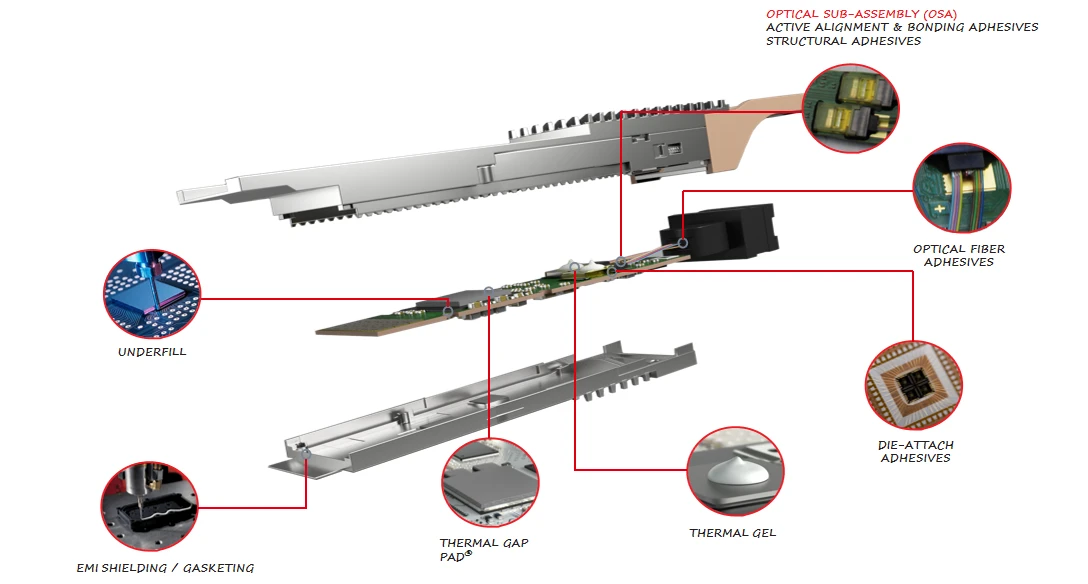
Optical Module Thermal Management sits at the heart of high-speed optical systems. Break the phrase down—Optical, Module, Thermal, Management—and you get light-driven devices, compact packaging, heat, and control. When Optical Module Thermal Management is done right, optical performance stays stable, signal drift drops, and lifespan stretches. When it’s off, things heat up fast—literally.
Thermal Interface Materials 101: From Grease to Liquid Metal
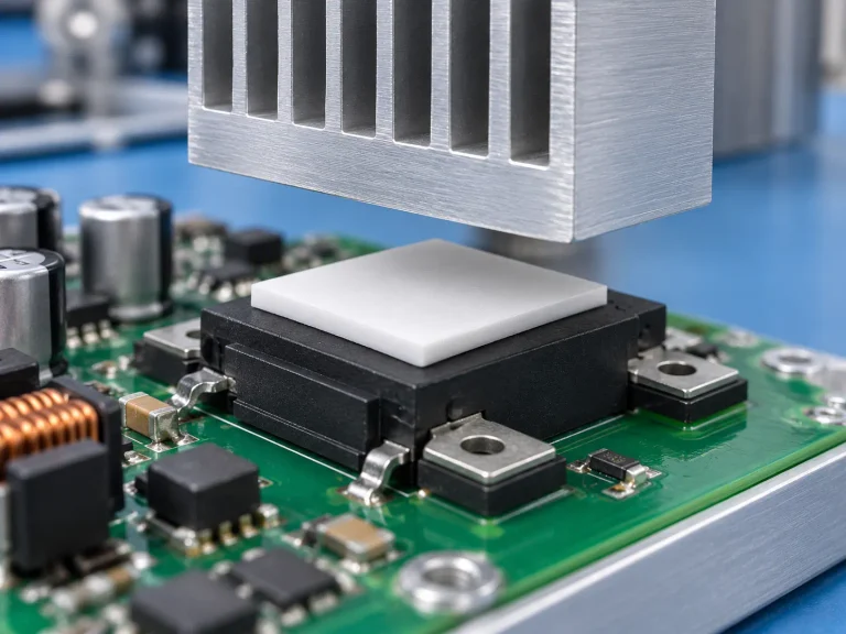
In Optical Module Thermal Management, the contact layer between the chip and the spreader often decides success.
- Material Categories in Thermal Interface Materials
- Soft Interfaces
- thermal grease: fills micro-voids, lowers interface resistance
- gap filler pads: handle uneven stacks
- Transitional Media
- phase-change compounds: soften near 50–60°C
- High-Conductivity Options
- liquid metal: extreme thermal conductivity, careful insulation needed
- Soft Interfaces
- Performance Drivers in TIM Selection
- Bulk thermal conductivity (W/m·K)
- Long-term pump-out resistance
- Compatibility with heat transfer paths
- Typical Thermal Interface Materials Data in Optical Module Thermal Management
| Material Type | Thermal Conductivity (W/m·K) | Typical Thickness (µm) | Interface Resistance (°C·cm²/W) |
|---|---|---|---|
| Thermal Grease | 3–8 | 20–50 | 0.05–0.15 |
| Gap Filler Pad | 1–6 | 200–1000 | 0.20–0.60 |
| Phase Change Material | 2–5 | 50–150 | 0.08–0.20 |
| Liquid Metal | 20–70 | 10–30 | 0.01–0.03 |
| Conductive Polymer | 5–15 | 30–80 | 0.04–0.12 |
In optical module thermal design, reducing interface resistance keeps junction temperature under control. That’s the quiet hero move in Optical Module Thermal Management.
Heat Spreader Fundamentals with Copper, Diamond, and Graphite
Once heat crosses the Thermal Interface Materials, spreading becomes the game.
- Core Heat Spreader Materials
- Metals
- copper: ~400 W/m·K, easy machining
- tungsten copper: tuned expansion match
- Carbon-Based
- graphite: strong in-plane thermal spreading
- diamond: extreme thermal conductivity, premium cost
- Ceramics
- Silicon carbide: balanced material properties
- Metals
- Thermal Spreading Logic in Optical Module Thermal Management
- Vertical conduction pulls heat from the die.
- Lateral spreading avoids hotspots under laser drivers.
- Even temperature improves heat dissipation across the housing.
- Matching Material to Optical Modules
- III-V compound lasers → diamond composites for tight junction limits
- Silicon germanium drivers → copper baseplates
- Co-packaged optics → graphite layers for planar spreading
Strong optical thermal control depends on aligning material properties with expansion rates. That keeps solder joints safe and performance steady. Teams working on Optical Module Thermal Management often test multiple spreaders before locking the stack.
Substrate & Package Bases – Ceramic, Aluminum Nitride, and Alumina
At the base of Optical Module Thermal Management, the Substrate carries both circuits and heat.
- Substrate Material Options
- ceramic families
- alumina: cost-effective, moderate conductivity
- aluminum nitride: high conductivity, strong dielectric strength
- Advanced Bases
- Silicon carbide: thermal match with power devices
- copper clad laminate: hybrid electrical routing
- ceramic families
- Functional Roles in Thermal Management
- Mechanical support for epitaxial layers
- Electrical insulation with stable dielectric behavior
- Heat path routing toward system sinks
- Packaging Stack in Optical Module Thermal Management
- Chip level
- die attach + TIM
- Intermediate
- package bases with controlled CTE
- System level
- chassis heat sink
- Chip level
Short take: better substrate choice equals smoother optical module thermal flow.
Engineers focused on Optical Module Thermal Management look closely at aluminum nitride when power density climbs above 5 W/cm². Lower thermal resistance at the base means fewer surprises in reliability testing.
For companies building next-gen optical engines, including teams at Sheen Materials, material pairing across Thermal Interface Materials, Heat Spreader, and Substrate layers defines the ceiling of performance. Get the stack right, and Optical Module Thermal Management turns from a headache into a competitive edge.
Why Thermal Management Matters in Optical Modules(I/O)?
Optical Module Thermal Management sounds technical, yet it’s really about keeping laser-driven hardware cool so signals stay clean and stable. From optical engines to copper bases, smart thermal control keeps performance steady and downtime low.
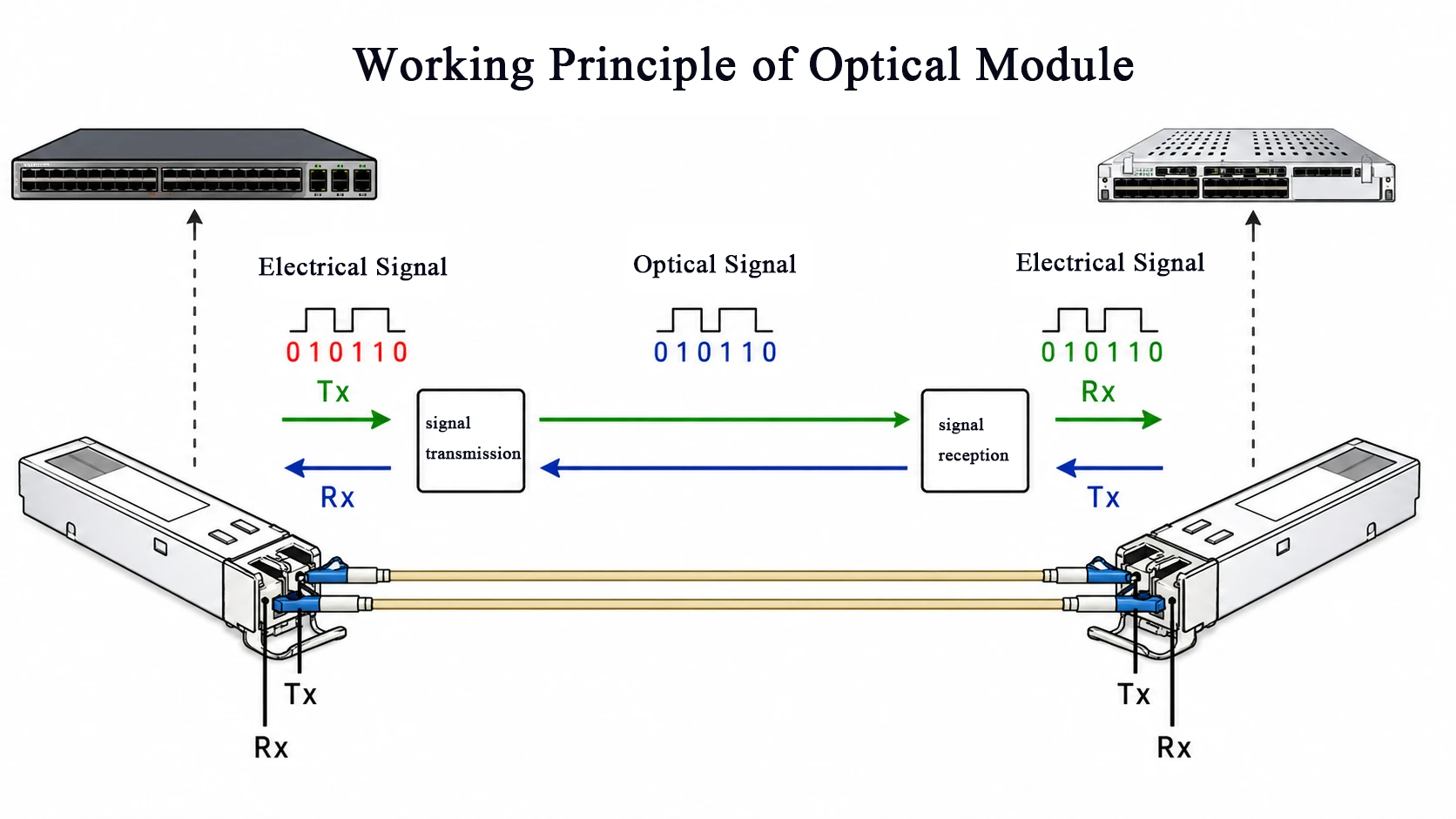
Preventing Hotspots with Thermal Pads and Gap Fillers
In Optical Module Thermal Management, stopping Hotspots is step zero.
- Core interface control
- Thermal Pads
- Act as a compliant Thermal Interface Material
- Improve Heat Transfer between the chip and the heat sink
- Gap Fillers
- Compensate for height tolerance
- Boost Heat Dissipation across uneven stacks
- Thermal Pads
- Material pairing logic
- Gallium arsenide die → soft pad contact
- Copper plate → optimized surface pressure
- Result → stronger Component Protection
For high-speed optical module cooling, even tiny air gaps wreck efficiency. Sheen Technology tunes pad thickness and compression rate so the optical module’s thermal path stays tight, not sloppy.
Maximizing Lifespan: Graphite vs. Silicon Carbide Spreaders
When extending Lifespan, Heat Spreaders matter.
| Material | Thermal Conductivity (W/m·K) | Density (g/cm³) | Key Material Properties | Reliability Impact |
|---|---|---|---|---|
| Graphite | 400–700 (in-plane) | ~2.2 | High lateral spread | Strong Performance stability |
| SiC | 120–270 | ~3.2 | High stiffness | Enhanced Reliability |
| Copper | ~385 | 8.9 | Isotropic conduction | Moderate lifespan |
| AlN | 140–180 | 3.3 | Electrical insulation | Balanced use |
Graphite wins on weight and lateral flow. Silicon Carbide shines in rigidity under laser cycling. In Optical Module Thermal Management, the choice shapes optical module thermal stability for years. Sheen Technology aligns spreader selection with power density, not hype.
Ensuring Stability through Epoxy Resin and Low-Stress Encapsulants
Thermal cycling hits harder than most expect. True Stability comes from smart Encapsulation.
- Protection stack
- Epoxy Resin
- Shield’s gold wires
- Blocks moisture ingress
- Low-Stress Encapsulants
- Reduce Thermal Stress
- Maintain Mechanical Integrity
- Epoxy Resin
- Material selection logic
- Silicone gel → flexibility
- UV resin → fast cure, tight seal
Good Optical Module Thermal Management is not just about moving heat. It’s about keeping optical alignment intact while temperatures swing. That’s how Component Protection turns into long-term optical module reliability—and why Sheen Technology keeps refining every layer in the thermal management system.
Types of Heat Sinks for Optical Modules
High-speed links push serious heat into tiny spaces. That’s why Optical Module Thermal Management is no small talk in data centers. From copper to diamond, each cooling path shapes how stable your optical module runs, how long it lasts, and how far performance can stretch.
Copper Fin Heat Sinks
In Optical Module Thermal Management, Copper remains a go-to thanks to its high Thermal conductivity and low Thermal resistance.
- Material Core
- Base design
- Thick copper base pulls heat directly from silicon.
- Reduces hotspot intensity at the source.
- Fin Geometry
- Dense Fins increase the heat dissipation area.
- Optimized spacing supports airflow or liquid contact.
- Base design
- Manufacturing Paths
- Stamping
- Cost-friendly for volume builds.
- Skived processing
- Continuous fin structure lowers interface loss.
- Stamping
For optical module cooling inside tight transceiver cages, copper fins connect die to ambient air or glycol loops with minimal loss. Sheen Technology tunes fin pitch and base thickness so Optical Module Thermal Management stays efficient without overloading rack airflow.
Aluminum Pin-Fin Arrays
When weight and airflow matter, Aluminum shines.
• Pin-fins expand surface exposure.
• Strong Convection improves Heat transfer in forced air systems.
• Lightweight structure reduces mechanical strain on boards.
Manufacturing usually relies on Extrusion, keeping cost practical while maintaining solid Thermal performance.
In many optical module platforms, airflow is king. Aluminum pin structures let cool air weave through the array instead of skimming across flat plates. That airflow behavior upgrades optical module thermal control without heavy metal mass. For operators balancing cost and performance, this approach fits neatly into scalable Optical Module Thermal Management plans.
Graphite Cold Plates
For higher densities, air just can’t keep up. That’s where Graphite and liquid systems enter serious Optical Module Thermal Management design.
- Thermal Spreading Layer
- High in-plane thermal conductivity
- Uniform Thermal spreading across the module surface
- Cold plate Integration
- Internal Channels
- Designed for balanced Liquid cooling flow
- Compatible with deionized water or dielectric fluids
- Structural Frame
- Lightweight composite backing
- Strong Fluid compatibility
- Internal Channels
Typical performance comparison in optical module cooling systems:
| Material System | In-Plane Conductivity (W/m·K) | Weight (g) | Cooling Medium | Typical Use Case |
|---|---|---|---|---|
| Copper Plate | 380 | 120 | Air/Glycol | 400G modules |
| Aluminum Plate | 205 | 75 | Air | 100G–200G |
| Graphite Plate | 600–1000 | 60 | Liquid | 800G+ modules |
| Hybrid Design | 450 | 85 | Liquid | Co-packaged optics |
Graphite spreads heat fast before liquid extracts it, stabilizing optical module temperature gradients. Sheen Technology integrates graphite cold plates into advanced Optical Module Thermal Management systems, where tight rack density demands smarter optical module heat management.
Diamond-Enhanced Spreader Blocks
When power density spikes in coherent engines, standard spreaders struggle. That’s where Diamond comes in.
- Heat leaves the indium phosphide die.
- A Thermal interface layer connects to a Heat spreader.
- CVD diamond rapidly transfers energy outward.
- The external sink manages final dissipation.
Key advantages in optical module thermal control:
- Ultra-high Thermal conductivity for extreme Hotspot management.
- Natural Electrical insulation, reducing the risk.
- Built for high-power density photonic engines.
Diamond-enhanced blocks are not cheap, sure. But in next-gen Optical Module Thermal Management, performance often outweighs cost. For ultra-fast links and compact optical engines, this approach keeps temperatures stable and signal integrity intact.
Across copper, aluminum, graphite, and diamond, the message is simple: smart Optical Module Thermal Management keeps optical module systems cool, reliable, and ready for higher speeds. And yes, getting that balance right is where real engineering shows up.
4 Common Cooling Methods Explained
Optical Module Thermal Management keeps high-speed links alive and stable. When heat builds up inside an optical module, performance drops fast. Smart thermal management of the optical module makes sure signals stay clean, and hardware lasts longer.
Conduction Cooling with Thermal Grease and Pads
In Optical Module Thermal Management, conduction is the most direct path for heat transfer.
- Core heat path
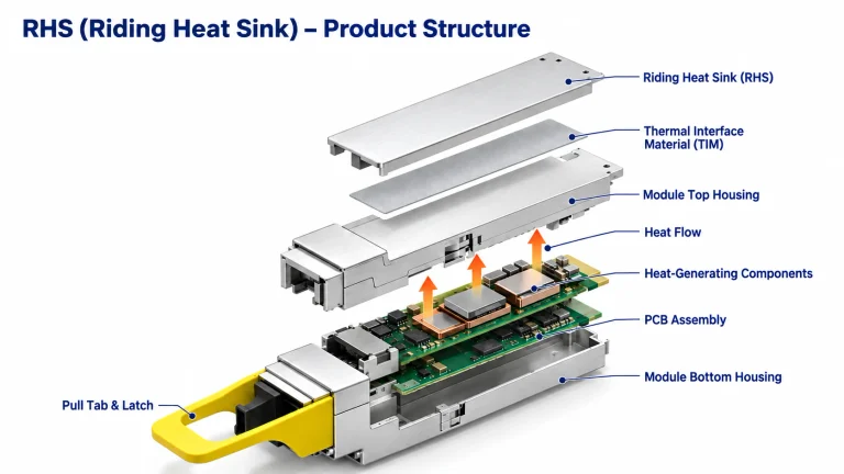
- Chip → thermal interface material (TIM) → baseplate → heat sink
- Thermal grease, pad, or gap filler reduces thermal resistance
- High thermal conductivity keeps junction temperature in check
- Material choices
- Silicone-based TIM for flexibility
- Phase-change pads for tighter contact
- Ceramic fillers for insulation
For optical module cooling, this method works great in compact transceivers. Sheen Technology fine-tunes TIM thickness to optimize Optical Module Thermal Management without squeezing the PCB too hard.
Dielectric Fluid Convection Systems
Optical Module Thermal Management often steps up to dielectric fluid cooling when power density climbs.
- Fluid loop design
- Pump drives circulation
- Cold plate spreads heat
- The heat exchanger releases it outside
- Inside the loop
- Coolant flow rate impacts convection
- Smart fluid dynamics modeling avoids hotspots
- Stable thermal management protects lasers
This setup supports advanced optical module heat control in data centers. Sheen Technology integrates sealed loops to keep optical module thermal loads stable even under burst traffic.
Liquid Metal Heat Pipe Integration
For tight layouts, Optical Module Thermal Management benefits from a heat pipe system.
- Internal structure
- Evaporator absorbs heat
- Liquid metal vaporizes through phase change
- Vapor moves to the condenser
- Wick structure returns fluid
- Why it works
- Extremely high thermal conductivity
- Passive heat transfer, no pump
- Ideal for compact optical engines
Optical module heat management gets quieter and lighter with this approach, especially in high-speed Optical Module Thermal Management designs.
Synthetic Oil Immersion Cooling
When power density spikes, immersion cooling becomes a serious option for Optical Module Thermal Management.
- Immersion setup
- Modules submerged in synthetic oil
- Oil acts as a dielectric fluid and a coolant
- Continuous fluid circulation improves heat dissipation
- System benefits
- Uniform temperature field
- Strong electrical insulation
- Lower overall thermal stress
This method supports next-gen optical module thermal management in AI clusters. Sheen Technology applies immersion-ready designs so Optical Module Thermal Management stays stable even in extreme compute racks.
Passive vs. Active Cooling: Which Wins?
Optical Module Thermal Management sounds technical, yet it’s really about keeping laser and transceiver hardware cool so performance doesn’t tank. From optical module heat control to full thermal management systems, the goal stays simple: move heat, stay stable.
Passive Cooling
In Optical Module Thermal Management, passive strategies rely on material science and geometry rather than motors or pumps.
- Core Heat Transfer Paths
- Conduction
- Heat sinks bonded with high-grade Thermal interface materials
- Copper bases spreading heat toward fin arrays
- Natural convection
- Vertical fin layouts to guide airflow
- Open-frame cages improve buoyancy-driven exchange
- Radiation
- Black anodized aluminum surfaces boost emissivity
- Conduction
- Enhanced Passive Devices
- Heat pipes
- Phase-change cycle moving heat from the laser die to the chassis wall
- Vapor chambers
- Planar heat spreading for dense optical module layouts
- Graphite sheets
- Lateral conduction across PCB hotspots
- Heat pipes
For moderate optical module power levels, this approach keeps Optical Module Thermal Management quiet, low-maintenance, and cost-friendly. No moving parts. Fewer failures. Sheen Technology often integrates these solutions into compact transceivers where stability matters more than brute-force cooling.
Active Cooling
When Optical Module Thermal Management must handle high-power III-V arrays, passive methods hit their ceiling. That’s where motion steps in.
• Fans enable forced convection, pushing air directly across fin stacks.
• Thermoelectric coolers (TECs) pump heat against the gradient for precise laser wavelength control.
• Liquid cooling loops with Pumps circulate coolant through micro cold plates.
• Advanced setups apply Refrigeration or microfluidics for extreme density.
1) Detect temperature rise.
2) Trigger control logic.
3) Increase airflow or coolant rate.
4) Stabilize junction temperature.
Performance Snapshot for Optical Module Thermal Management
| Cooling Method | Typical Heat Flux (W/cm²) | Temp Stability (±°C) | Power Overhead (%) |
|---|---|---|---|
| Heat Sink + Natural Convection | 5–10 | 3–5 | 0 |
| Heat Pipe Assisted | 10–20 | 2–4 | 0 |
| Fan + Forced Convection | 15–30 | 2–3 | 5–8 |
| TEC + Liquid Cooling | 30–60 | 0.1–1 | 10–20 |
Active optical module cooling costs more energy, yet it delivers tight wavelength control and long-term reliability. In dense data links, Optical Module Thermal Management often blends both styles. Sheen Technology supports hybrid designs where passive spreading meets active precision, keeping optical performance steady even when power levels climb.
Optical Module Thermal Management Best Practices
Optical Module Thermal Management is not just about moving heat; it’s about keeping performance steady when data rates climb and power density spikes. Good optical module cooling keeps lasers stable, drivers safe, and your network running smoothly.
Optimize Interfaces with Phase Change Materials
In Optical Module Thermal Management, the weakest link is often the interfaces between die and spreader. Smart thermal management starts here.
- Interface control strategy
- Material layer
- Apply phase change materials with matched material properties to silicon and copper.
- Target low thermal resistance under 60 µm bond-line thickness.
- Surface prep
- Polish contact zones to reduce voids affecting heat transfer.
- Verify flatness below 20 µm across the optical module base.
- Performance validation
- Measure delta-T under 2 W/mm² heat flux.
- Track effective thermal conductivity during burn-in cycling.
- Material layer
For stable Optical Module Thermal Management, PCM activation temperature must align with peak junction rise. Too high, and gaps stay open. Too low, and the pump-out becomes real. Optical thermal control lives or dies at this junction.
Sheen Technology tunes interface stacks so Optical Module Thermal Management stays consistent across 100G to 800G platforms.
Choose Packaging Materials: Silicon Carbide vs. Copper Clad Laminate
Material selection shapes long-term Optical Module Thermal Management efficiency.
- Substrate comparison framework
- Silicon carbide
- High thermal conductivity (>120 W/m·K).
- Strong stiffness, reducing warpage in dense optical modules.
- Better high-power heat dissipation.
- Copper-clad laminate
- Moderate conductivity (10–25 W/m·K).
- Easier material selection for cost-sensitive builds.
- Mature PCB integration for driver circuits.
- Silicon carbide
Decision path for packaging materials in Optical Module Thermal Management:
- Define heat density per channel.
- Match the substrate to the expected junction temperature ceiling.
- Validate solder fatigue under thermal cycling.
For next-gen optical module thermal management, silicon carbide shines in high-power coherent designs, while copper-clad laminate keeps pluggables affordable and practical.
Refine Interconnects Using Gold Wire and Conductive Epoxy
Electrical paths double as thermal bridges in Optical Module Thermal Management.
- Interconnect architecture
- Gold wire bonding
- High electrical conductivity.
- Stable under repeated bonding heat.
- Conductive epoxy
- Absorbs CTE mismatch.
- Supports localized heat dissipation around driver ICs.
- Hybrid bonding
- Combine gold wire loops with epoxy anchor points to balance stress.
- Gold wire bonding
Execution flow:
- Control loop height below 150 µm to reduce inductance.
- Optimize bonding force to avoid pad lift-off.
- Inspect shear strength after 500 thermal cycles.
In Optical Module Thermal Management, poor interconnect design traps heat at pads. Tight bonding keeps optical module thermal management predictable, especially at high baud rates. Sheen Technology fine-tunes bonding recipes to stabilize both current flow and temperature rise.
Select Cooling Fluids: Glycol Solution or Refrigerant
Cooling fluid choice defines the outer layer of Optical Module Thermal Management.
- Cooling system hierarchy
- Liquid loop using glycol solution
- Closed-loop design for data centers.
- Stable fluid properties across 0–60°C.
- Suitable for moderate heat transfer loads.
- Two-phase loop using refrigerant
- Evaporation absorbs high heat dissipation peaks.
- Ideal for dense AI-driven optical module racks.
- Liquid loop using glycol solution
Selection checklist:
- ✓ Required heat flux above 3 W/cm²? Consider a refrigerant.
- ✓ Need simpler maintenance? Glycol works fine.
- ✓ Tight rack spacing? Two-phase improves the Optical Module Thermal Management margin.
When Optical Module Thermal Management is designed end-to-end—from chip interface to cooling fluids—the optical module runs cooler, lasts longer, and handles traffic spikes without drama. That’s the kind of optical thermal management mindset Sheen Technology builds into every platform.
FAQs about Optical Module Thermal Management
What materials are most trusted for Optical Module Thermal Management in high-power transceivers?
Heat inside 400G–800G modules builds fast around the silicon wafer, indium phosphide wafer, and other III-V compound chips. Material choice decides survival.
1) Heat spreaders
- Copper and aluminum handle mainstream conduction.
- Graphite smooths lateral heat flow across dense optical engines.
- Diamond and silicon carbide step in where power density spikes.
- Tungsten copper or beryllium oxide serves niche high-load designs.
2) Thermal interface materials
- Thermal grease and phase change material fit cost-sensitive builds.
- Thermal pad and gap filler correct surface unevenness.
- Liquid metal delivers extreme conductivity between the chip and copper base.
- Thermal adhesive or conductive polymer supports structural bonding.
Buyers balancing lifetime and budget often pair a copper spreader with graphite reinforcement and a stable phase change material layer to prevent hotspot drama.
Why do some manufacturers choose liquid metal instead of thermal grease?
The decision is emotional as much as technical: temperature margin equals product reputation.
- Liquid metal forms an ultra-thin bond line between a gallium arsenide wafer or silicon germanium die and a copper or aluminum base.
- Junction temperature drops noticeably in compact coherent engines.
- Long-term pump-out risk is lower compared with conventional thermal grease under cycling.
However, integration demands care:
- Compatible substrates such as ceramic substrate, aluminum nitride, or silicon carbide reduce corrosion risk.
- Controlled assembly with solder paste, gold wire, or copper wire interconnects prevents contamination.
- Protective epoxy resin or low-stress encapsulant seals the system.
In dense optical cages where every degree counts, liquid metal becomes a strategic move, not just a material swap.
How do cooling fluids and packaging materials work together in data center optical modules?
When airflow fails, fluid steps in—and packaging must endure the pressure.
Short view: cooling medium, substrate, and encapsulation must act as one system.
| Function | Typical Choices | Practical Impact |
|---|---|---|
| Cooling fluid | Dielectric fluid, glycol solution, synthetic oil, refrigerant | Stable heat transfer without shorting optics |
| Substrate/base | Aluminum nitride, alumina, silicon carbide, copper clad laminate | Electrical insulation + mechanical strength |
| Encapsulation | Silicone gel, potting compound, molding compound, UV-curable resin | Shields gold wire, solder ball, conductive epoxy joints |
| Optical elements | Silica glass, fused silica, sapphire | Maintains clarity under thermal cycling |
In immersion-cooled racks, dielectric fluid flows around modules built on ceramic substrate or glass-epoxy laminate bases. Inside, silica glass lenses and silicon nitride structures stay protected by dielectric encapsulant.
The tension lies here: fluid removes heat, but packaging preserves precision. Optical Module Thermal Management succeeds only when both sides respect each other.