-
ADD: Building 2, No. 8 Hengzhutang Road, Dongguan
-
Phone: +86 135 4224 3751

How to Properly Install a Non-Silicone Thermal Pad for CPUs
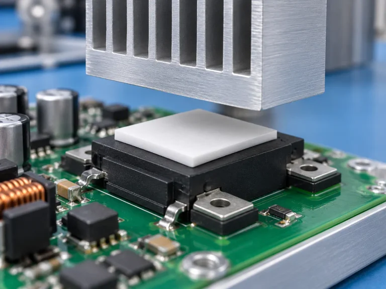
A Non-Silicone Thermal Pad might look like a quiet little square of material, but when your CPUs are running hot, and your RMA numbers start creeping up, that “little square” suddenly feels like the hero—or the villain—of the whole operation. In high-density servers and performance rigs, heat isn’t just a side effect. It’s the silent budget killer. One sloppy install, a speck of residue, a pad cut a hair too small, and your cooling system is basically wearing flip-flops in a snowstorm.
Data centers are pushing chips harder every year; Uptime Institute’s 2024 reports show rising rack densities driving tighter thermal margins across facilities. That means there’s zero room for guesswork. As a senior thermal engineer at Sheen Electronic Technology put it in a 2025 briefing, “Installation discipline matters as much as material selection.”
This guide gets straight to it—how to install it right, protect performance at scale, and keep your operation cool when the pressure’s on.
Key Points: Non-Silicone Thermal Pad Essentials
➔ Surface Prep: Clean, inspect flatness, and verify dielectric strength to minimize air gaps and electrical risk.
➔ Gap Filling: Measure tolerances and select pad thickness for optimal conformability and stable thermal conductivity.
➔ Precision Cutting: Use die-cutting on sheet or roll stock for accurate alignment and uniform heat transfer.
➔ Long-Term Stability: Track thermal impedance drift, ensure RoHS/REACH compliance, and assess durability under extended operating temperatures.
5 Steps To Prepare Your CPU Surface
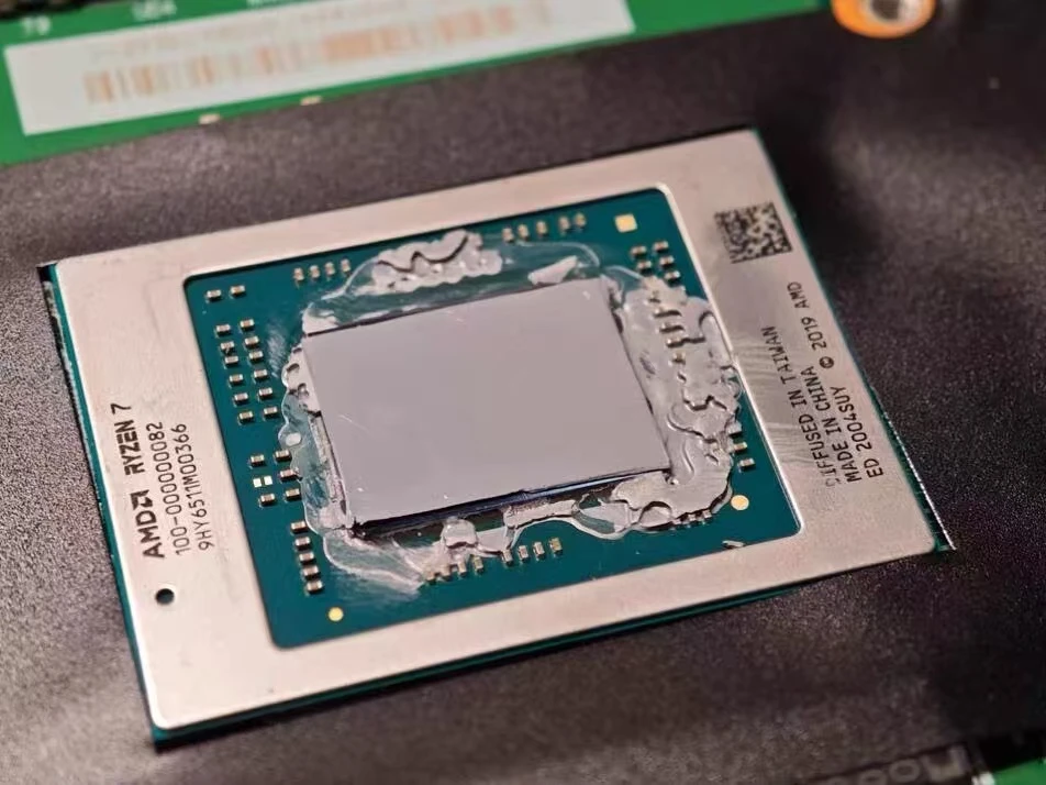
Getting your CPU ready for a Non-Silicone Thermal Pad install isn’t rocket science, but skipping prep can wreck heat flow fast. A clean, flat, well-checked surface helps every thermal pad—especially a non-silicone thermal pad—perform at its best.
Step 1: Cleaning Residues for Optimal Conformability
A proper wipe-down of the CPU surface sets the tone for everything that follows.
- Target contaminants:
- Old thermal paste residue
- Finger oils
- Oxidation spots
- Recommended tools:
- High-purity isopropyl alcohol
- Fresh lint-free cloth
- Approved cleaning solution
When handling residue removal, keep pressure even and avoid scratching the metal. A spotless surface preparation routine allows the polymer base of a Non-Silicone Thermal Pad to sit flush, improving wetting and lowering interface resistance. A non-silicone pad can’t compensate for dirt, so don’t cut corners.
Step 2: Inspecting Surface Flatness and Hardness
Before mounting a heat sink, inspect the CPU lid and heat spreader carefully.
- Perform a basic flatness test using a straight edge.
- Conduct light surface inspection under angled lighting.
- If needed, arrange a microscopic examination for deeper flaws.
For quality control teams:
- Surface integrity
- Check coating wear
- Confirm no dents
- Material review
- Light hardness assessment
- Verify material integrity
Even minor warping increases air gaps. A Non-Silicone Thermal Pad depends on controlled compression; uneven surfaces reduce contact efficiency.
Step 3: Evaluating Gap Filling Requirements
Correct gap measurement avoids under- or over-compression.
- Measure:
- Component height
- Mounting tolerance
- Board deflection
- Match:
- Proper thermal pad thickness
- Right thermal interface material
- Balanced pressure distribution
A well-chosen non-silicone thermal interface pad improves void reduction and keeps thermal conductivity stable across temperature swings. Many engineers sourcing from Sheen Electronic Technology prefer tailored thickness options to fine-tune heat sink mounting results.
Step 4: Cutting Pads in Sheet Form with Precision Die-Cutting
Working from a thermal pad sheet demands accuracy.
- Equipment:
- Calibrated die-cutting machine
- Controls:
- Verified cutting accuracy
- Stable sheet material handling
- Output:
- Clean pad shape
- True custom sizing
- Consistent precise cuts
Poor trimming causes misalignment and edge lift. A properly cut Non-Silicone Thermal Pad sits squarely over hot zones, especially in power modules where tolerances are tight.
Step 5: Verifying Dielectric Strength before Heat Sink Attachment
Thermal control is only half the job; insulation matters too.
- Electrical checks:
- Rated dielectric strength
- Confirmed volume resistivity
- Controlled voltage test
- Protection goals:
- Reliable electrical insulation
- Strong short circuit prevention
- Long-term component protection
A high-grade thermal pad material must show stable insulating properties before final assembly. Brands like Sheen Electronic Technology test each Non-Silicone Thermal Pad to meet strict breakdown standards, giving power electronics that extra layer of safety.
Prep it right, and your non-silicone pad will do its job—quietly, efficiently, and without drama.
Since Sheen Electronic Technology’s inception 18 years ago, we have accumulated extensive experience and achieved significant results in the research, development, and production of thermal conductive materials and silicone foam materials.
Especially in the research and development and production of Non-Silicone Thermal Pads, we have established long-term partnerships with world-class automotive manufacturers and data centers over the past 25 years, and we expect to reach an annual production volume of over 5 million units in 2026, 2027, and 2028.
Is Pad Alignment That Critical?
Getting pad alignment right is not just some picky engineering habit. When a Non-Silicone Thermal Pad sits between a chip and a heat sink, tiny shifts can mess with heat transfer in a big way. From thermal conductivity to long-term reliability, alignment quietly shapes performance.
Impact of Misalignment on Thermal Conductivity
When a Non-Silicone Thermal Pad is even slightly off-center, the real trouble starts at the interface.
- Changes in interface area
- Reduced physical contact shrinks the active heat transfer path.
- Smaller contact zones increase contact resistance.
- Gaps trap air, which performs terribly in terms of thermal conductivity.
- Thermal consequences
- Local temperature increase near the chip edge.
- Uneven heat flow across the pad surface.
- Gradual performance degradation in high-load devices.
- High-power scenarios
- In LED modules, brightness drift is due to poor cooling.
- In automotive ECUs, unstable readings occur under vibration.
- In CPUs, throttling is caused by rising junction temperature.
A correctly placed Non-Silicone Thermal Pad keeps the interface area fully engaged, allowing the pad’s thermal conductivity rating to actually mean something in real-world use.
How Conformability and Compressibility Affect Contact
Not all pads behave the same under pressure. A good Non-Silicone Thermal Pad relies on balanced conformability and compressibility to fight back against messy surfaces.
- Key performance factors:
- Adequate compressibility to absorb tolerance stack-ups.
- Strong conformability to match surface irregularities.
- Stable contact pressure without over-squeezing.
Here’s how it plays out in practice:
- The pad meets the heat source.
- Controlled compression reduces air gaps.
- Even pressure distribution forms across the thermal interface material.
- Effective contact lowers total thermal resistance.
A recent 2025 thermal management outlook from MarketsandMarkets noted:
“As power densities rise in automotive and AI hardware, interface materials with reliable compression recovery and void minimization are seeing accelerated adoption.”
That’s why silicone-free thermal pad solutions are gaining traction. Brands like Sheen Electronic Technology fine-tune filler loading and polymer structure so the pad adapts without pumping out or cracking over time. It’s less drama, more stable cooling.
Ensuring Uniform Heat Dissipation across the Interface
Uniform cooling is not luck. It comes from controlled mechanics across the full thermal interface.
- Mechanical alignment
- Center the Non-Silicone Thermal Pad over the CPU die or power module.
- Match pad size to the heat spreader footprint.
- Avoid edge overhang that disrupts even pressure.
- Pressure management
- Calibrated mounting torque ensures consistent contact.
- Balanced clamping prevents tilt.
- Stable force improves uniform heat dissipation.
- System-level outcome
- Heat flows evenly into the cooling solution.
- Fewer hotspots at the corners.
- Long-term reliability across operating cycles.
When a Non-Silicone Thermal Pad sits flat, centered, and evenly compressed, the whole stack works like it should. No hot edges. No weird spikes. Just steady uniform heat dissipation and dependable performance, day in and day out.
Server Farms: Long-Term Pad Stability
Server farms run hot, day and night, no breaks. Keeping chips cool over years takes more than airflow. A well-chosen Non-Silicone Thermal Pad keeps performance steady and avoids messy surprises in high-density racks.
Assessing Durability under Extended Operating Temperature Range
Long-term stability of a Non-Silicone Thermal Pad in harsh racks depends on tight control across materials and mechanics:
- Material Science Validation
- Polymer base
- Check resistance to high operating temperature swings.
- Track changes in elasticity under continuous CPU cooling pressure.
- Ceramic fillers
- Confirm dispersion stability to prevent separation.
- Maintain consistent durability across extended range exposure.
- Polymer base
- Mechanical Integrity Under Load
- Compression set
- Measure recovery after months of clamping force.
- Surface conformity
- Ensure stable contact to avoid performance degradation in dense CPU cooling layouts.
- Compression set
- Thermal Reliability Benchmarks
- Continuous burn-in tests
- Cyclic heat ramp simulations
- Cross-check with real rack telemetry
A quality thermal pad built without silicone bleed helps avoid contamination, and a silicone-free thermal interface often keeps hardware cleaner over time. Sheen Electronic Technology focuses on stable filler bonding, so the Non-Silicone Thermal Pad holds up when the heat just won’t quit.
RoHS and REACH Compliance for High-Volume Deployments
In massive rollouts, paperwork matters as much as watts.
- Regulatory Alignment
- RoHS compliance
- Restrict hazardous substances across high-volume production.
- REACH compliance
- Verify chemical registration and safe use in the supply chain.
- RoHS compliance
- Manufacturing Standards
- Raw material audits
- Batch traceability
- Ongoing material safety reviews
- Supply Chain Control
- Vendor qualification
- Documentation storage
- Environmental regulations monitoring
A certified Non-Silicone Thermal Pad supports corporate ESG goals and keeps audits smooth. Fewer restricted substances, fewer late-night compliance headaches.
Monitoring Thermal Impedance Drift over Time
Long service life demands steady numbers.
- Baseline Establishment
- Record initial thermal impedance after installation.
- Log compressibility and contact resistance.
- Ongoing Performance Monitoring
- Data logging from onboard sensors
- Scheduled drift analysis every quarter
- Compare against expected long-term stability curves
- Failure Signal Review
- Rising impedance
- Reduced heat dissipation
- Shortened component lifespan
When drift appears, root-cause checks focus on filler migration or material fatigue. A reliable Non-Silicone Thermal Pad keeps impedance creep minimal, protecting uptime. That’s why data centers working with Sheen Electronic Technology prioritize stable, silicone-free thermal pad solutions that stay consistent long after installation.
FAQs about Non-Silicone Thermal Pad
What makes a Non-Silicone Thermal Pad suitable for power electronics?
In high-load power electronics and automotive electronics, stability matters more than softness.
A typical Non-Silicone Thermal Pad is built with:
(1) Polymer matrix for structural stability;
(2) Ceramic fillers, such as boron nitride or aluminum oxide, to boost thermal conductivity;
(3) Optional graphite particles or fiber reinforcement for added durability.
Performance highlights:
(1)Low and stable thermal impedance;
(2) Wide operating temperature range;
(3)Reliable heat dissipation under compression.
No silicone bleed means cleaner heat sink attachment and longer service life for LED modules and dense component layouts.
How does compressibility affect gap filling at the component interface?
A pad must adapt without collapsing.
Key mechanical balance:
(1) Compressibility → fills uneven surfaces;
(2) Conformability → reduces trapped air;
(3) Hardness & tensile strength → prevent over-squeeze;
(4) Durability → withstands thermal cycling.
At the component interface, proper compression lowers thermal impedance and maintains stable contact pressure during operation. Too soft causes pump-out; too hard leaves gaps. Precision in thickness selection is critical.
What formats and compliance standards should buyers consider?
Procurement decisions often depend on processing flexibility and certification.
Available formats:
(1) Sheet form for manual cutting;
(2) Precision die-cutting for custom shapes
(3) Roll stock for automated lines;
(4) Optional adhesive backing for quick placement.
Compliance factors to review:
(1) RoHS compliance;
(2) REACH compliance;
(3) Halogen-free options;
(4) UL certification and a defined flammability rating
Correct storage conditions preserve hardness and thermal performance, protecting the material before installation.
How is electrical insulation performance verified?
For sensitive circuits, insulation is non-negotiable.
Core electrical indicators:
| Parameter | What It Confirms | Why It Matters |
|---|---|---|
| Dielectric strength | Resistance to electrical stress | Prevents short circuits |
| Breakdown voltage | Maximum safe voltage | Ensures reliability under load |
| Volume resistivity | Internal insulation stability | Protects fine-pitch layouts |
| Electrical insulation | Overall safety barrier | Critical for power modules |
Testing is typically completed before final heat sink attachment, ensuring safe integration into compact assemblies.