-
ADD: Building 2, No. 8 Hengzhutang Road, Dongguan
-
Phone: +86 135 4224 3751

Don’t Guess! How to Choose the Thickness of Thermal Pads Properly
Discussing heat dissipation without considering thermal conductivity is ineffective optimization. Based on thousands of customer on-site debugging cases, we’ve identified a key point: mismatched thickness and compression ratio of thermal pads are the most common and easily overlooked causes of heat dissipation failures for hardware engineers. The rate of ineffective heat dissipation due to this error far exceeds that caused by defects in the thermal conductive material itself.
How to choose the thickness of thermal pads isn’t a minor call—it’s the difference between smooth performance and a meltdown in production lines.
Guessing gaps or eyeballing fit can wreck flow, spike temps, and kill reliability at scale.
Gartner and IDC research highlights rising demand for precise thermal interface design across electronics manufacturing supply chains.
Based on our 18 years of experience in thermal management R&D and manufacturing at Sheen Materials, we’ve identified two major misconceptions in the industry regarding assembly.
- First, some staff blindly select excessively thick thermal pads. When the gap between the chip and the heatsink is too small, and the assembly clamping pressure is insufficient, overly thick thermal pads cannot fully wet and adhere, causing a sharp increase in interfacial thermal resistance. This directly results in the thermal pad losing its heat dissipation capacity.
- Second, the selected thermal pads are too thin. Overly thin thermal pads cannot fill the assembly gaps caused by component assembly tolerances and housing deformation. A large amount of air remains at the contact surface; air has extremely low thermal conductivity, directly blocking the heat conduction path.
Besides the common misconception about assembling thermal conductive materials, there’s another fatal flaw: the tighter the screws, the better the heat dissipation.
Many engineers overtighten the fasteners during assembly, causing the thermal conductive silicone to compress beyond the critical 30% limit.
The thermal conductive silicone relies on oriented alumina and boron nitride fillers to build heat conduction pathways. Overcompression will crush and break the filler skeleton, disrupting the internal heat conduction chain and directly causing a significant decrease in thermal conductivity. The higher the pressure, the worse the heat dissipation.
Selecting thermal pads is never simply a matter of comparing thermal conductivity parameters; the core is gap fit and compression ratio control.
At Sheen Materialas, we abandon the one-size-fits-all supply model. We provide customers with specific and feasible solutions at every stage, from solution design and mass production to logistics and assembly.
For example:
- Before sales, we conduct research on four core data points for the customer: equipment assembly gaps, locking torque, housing deformation tolerances, and component power, to match the optimal pad thickness.
- We simultaneously provide officially recommended compression ratio ranges, clearly stating the safe compression threshold to avoid the risk of overload compression damage.
For projects with structural constraints, we simultaneously provide two or more alternative material options, balancing assembly feasibility and heat dissipation stability, and precisely avoiding assembly heat dissipation blind spots.
How to choose the thickness of thermal pads
- Gap Measurement: Use feeler gauges or laser tools to determine component-to-heatsink clearance and select a pad that fills the gap.
- Thermal Performance: Match pad conductivity and thickness to your device’s power density for optimal junction temperature.
- Tolerance Control: Tight thickness tolerance ensures consistent contact pressure, preventing thermal resistance variation across modules.
- Surface & Compressibility: For rough or uneven surfaces, choose pads (e.g., silicone or elastomeric) with high compressibility and stable dielectric strength.
4 Key Factors Determining Thermal-Pad Thickness
Picking pad thickness isn’t guesswork—it’s about balancing fit, pressure, and heat flow. If you’ve been wondering how to choose the thickness of thermal pads, break it into a few real-world checks. The right call keeps chips cool, avoids air pockets, and stabilizes performance without over-compressing materials.
Thermal Conductivity vs. Heat Dissipation Requirements
When people ask how to choose thermal pad thickness, they often forget that thermal conductivity and thickness interact. A thicker pad can increase thermal resistance even if the material has high watts per meter-kelvin ratings.
- High heat flux devices need thinner paths
- Larger gaps demand compromise between fill and heat transfer
- Poor choices raise the temperature gradient across the interface
Typical comparison:
| Material Type | Thickness (mm) | Material | Thermal Conductivity (W/m·K) | Thermal Resistance | High Temperature Resistance | Breakdown voltage(@AC) |
|---|---|---|---|---|---|---|
| SC800FG | 0.23 | silicone + glass fiber | 0.8 | 0.85゚C*in2/W | -40~200℃ | >4KV |
| SC900FG-16 | 0.23 | silicone + glass fiber | 1.6 | 0.6゚C*in2/W | -40~200℃ | 5KV |
| SC900FG | 0.3 | silicone + glass fiber | 1.0 | 0.83゚C*in2/W | -40~200℃ | >4KV |
| SC1000FG | 0.25 | silicone + glass fiber | 3.5 | 0.34 ゚C*in2/W | -40~200℃ | 4KV |
| SF500-PI | 0.3 | silicone +PI | 3.0 | 0.33゚C*in2/W | -40~200℃ | >4KV |
At Sheen Materials, for example, we adjust the choice of thermal interface materials so that you don’t experience poor heat dissipation due to excessive thickness.
Component Clearance and Gap Filling Explained
If you’re figuring out how to choose the thickness of thermal pads, start with component clearance.
- Measure interface gap after assembly mock-up
- Add margin for assembly tolerance
- Ensure full gap filling without forcing stress
Nested view:
- Clearance check
- PCB to heatsink distance
- Variations in component spacing
- Contact behavior
- Adequate contact pressure
- No trapped air gaps
Too thin? You lose surface contact. Too thick? You bend boards.
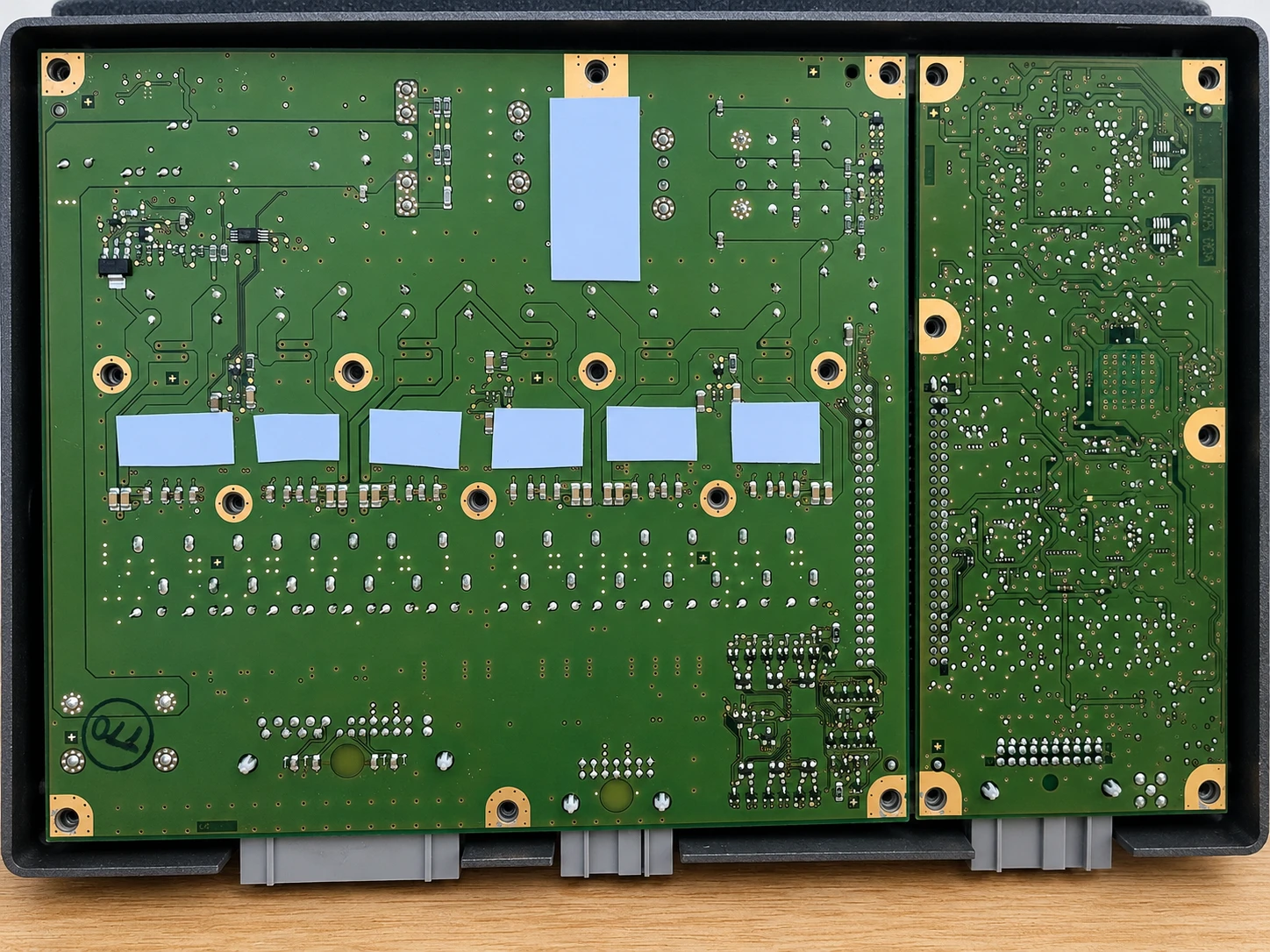
Thickness Tolerance’s Effect on Junction Temperature
A small shift in thickness tolerance can swing junction temperature more than expected. That’s why consistent pad specs matter for thermal management.
Short breakdown:
- Tight tolerance → stable thermal performance
- Wide tolerance → uneven heat path
- Poor control → reduced device reliability
Sheen Materials keeps tight production ranges, helping control temperature across processors and power modules.
Surface Topography and Compressibility Considerations
Not every surface is smooth. Surface topography and surface roughness decide how much the pad must deform.
Think in layers:
- Surface condition
- Rough aluminum → needs higher compressibility
- Polished copper → lower deformation needed
- Material response
- Elastic pads improve contact area
- Excess pad compression increases thermal impedance
Quick symbols to remember:
• Rough surface → softer pad
• Flat surface → thinner pad
• High pressure → watch material properties
If you’re still asking how to choose the thickness of thermal pads, it often comes down to matching material deformation with real hardware geometry. Get that right, and everything else falls into place.
How To Choose The Thickness Of Thermal Pads Using Measurements
Picking pad thickness isn’t guesswork. If you’ve ever wondered how to choose the thickness of thermal pads without frying components or losing contact, it comes down to clean measurements, simple math, and a quick sanity check on insulation and heat limits. Get these right, and your setup just works.
Measuring Gap Height: Precision Techniques and Tools
Getting gap height right is the whole game when you decide how to choose the thickness of thermal pads.
- Quick toolkit:
- feeler gauges
- calipers
- micrometers
- optical measurement rigs
1) Start with a dry fit
2) Slide feeler gauges until resistance feels even
3) Cross-check with calipers at multiple points
- Pro tip: slight compression (≈10–30%) is normal
Now layer it properly:
- Measurement flow
- Surface prep
- Clean contacts
- Remove old paste
- Primary read
- Use precision tools like gauges
- Verification
- Re-measure corners
- Watch for tilt or uneven pressure
- Surface prep
Uneven boards lie. Soft pads hide mistakes. Always measure twice.
This is how to choose thermal pad thickness without guesswork.
Calculating Thermal Resistance from Thickness Data
Once thickness is known, turn it into thermal resistance.
- Core idea:
- thicker pad → higher resistance
- better thermal conductivity → lower resistance
Steps that actually matter:
1) Note pad thickness (mm)
2) Check material thermal conductivity (W/m·K)
3) Estimate resistance across the interface material
Nested breakdown:
- Heat path logic
- Source
- GPU, VRM, memory
- Transfer
- Pad thickness from your thickness data
- Output
- Heatsink efficiency
- Source
Small checks:
- If temps spike, thickness may be too large
- If contact is poor, pad may be too thin
This part answers how to choose the thickness of thermal pads with real numbers, not vibes.
Verifying Operating Temperature Range with Dielectric Strength
Now don’t ignore safety. Pads aren’t just for heat—they insulate too.
- Key checks:
- operating temperature range
- dielectric strength
- thermal stability
Sequence to validate:
1) Match pad rating to peak device temp
2) Confirm electrical insulation needs
3) Check voltage breakdown limits
Deep structure:
- Reliability layer
- Thermal side
- Material properties hold up under load
- Electrical side
- Prevent shorts in high-density layouts
- Compliance
- Align with safety standards
- Thermal side
Too hot? Pad degrades. Too weak? Insulation fails.
This final check closes the loop on how to choose the thickness of thermal pads so your system runs cool and safe, not just cool for a minute.
How To Choose The Thickness Of Thermal Pads For Power Modules
Getting clear on how to choose the thickness of thermal pads can feel a bit fiddly, but it really comes down to matching gap size, pressure, and heat flow. If you’ve ever guessed and hoped for the best, yeah—that’s where trouble starts. Dial it in right, and your module runs cooler, longer, and way more stable.
Matching Power Density to Silicone-Based vs. Graphite Composite Pads
When thinking about how to choose the thickness of thermal pads, material choice sits right beside thickness. Power density drives everything—push it too high with the wrong interface material, and heat just lingers.
- Core decision path:
- Identify thermal conductivity needs from actual load
- Map that to material selection
- Silicone route
- Works well for electrical isolation
- Handles uneven surfaces with softer compression
- Graphite composite route
- Excels in lateral heat transfer
- Better for high-density hotspots
- Thickness tuning:
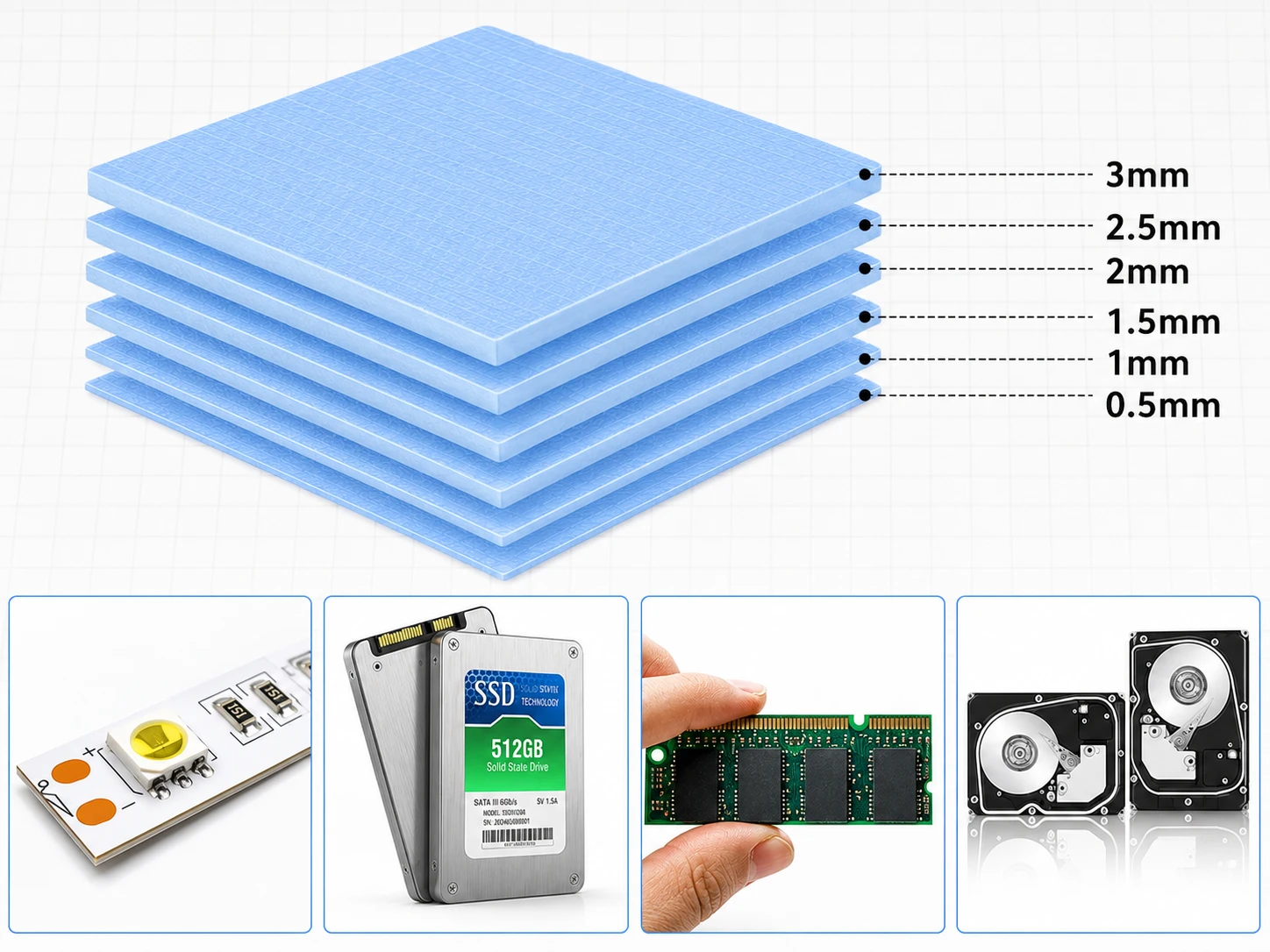
- Thin pads (0.5–1 mm): tighter interfaces, lower resistance
- Mid-range (1–2 mm): balance gaps and pressure
- Thick pads (2 mm+): only when tolerances demand it
A 2025 IDC thermal management brief noted:
“High-density power modules increasingly favor hybrid pad strategies, combining graphite layers with compliant silicone to balance conductivity and insulation.”
Brands like Sheen Materials already align products with this hybrid thinking, making how to choose the thickness of thermal pads less guessy and more data-driven.
Ensuring Vibration Resistance and Long-Term Reliability
Dialing in how to choose the thickness of thermal pads isn’t just about heat—it’s about staying put over time. Vibration resistance and mechanical stability matter more than most expect.
- Key reliability stack:
- Surface grip (tack level)
- Compression recovery
- Reinforcement layers
- Multi-step check:
- Evaluate thermal cycling exposure
- Measure compression set after repeated load
- Inspect for material fatigue and cracking
Short takeaways:
- Too thick → pump-out risk
- Too thin → poor contact
- Just right → stable durability and stress resistance
Regulatory Checklist: UL, RoHS, and Flammability Standards
If you’re still figuring out how to choose the thickness of thermal pads, don’t skip compliance—it’s not optional. The right thickness won’t matter if the material fails certification.
- Compliance flow:
- Regulatory compliance
- UL file verification
- Flammability ratings (V-0 preferred)
- Environmental layer
- RoHS compliance
- Halogen-free confirmation
- Documentation
- MSDS sheets
- Traceable safety certifications
- Regulatory compliance
Quick symbols to remember:
- ✔ UL recognized
- ✔ RoHS aligned
- ✔ Meets industry standards
Sheen Materials keeps documentation tight, which saves time when scaling production. And yeah, when someone asks again how to choose the thickness of thermal pads, the real answer blends physics, durability, and compliance—not just a number on a spec sheet.