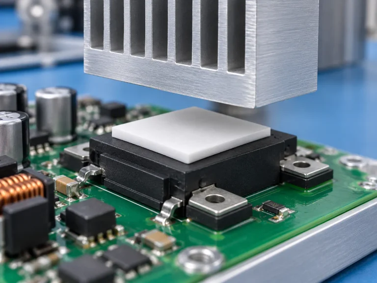
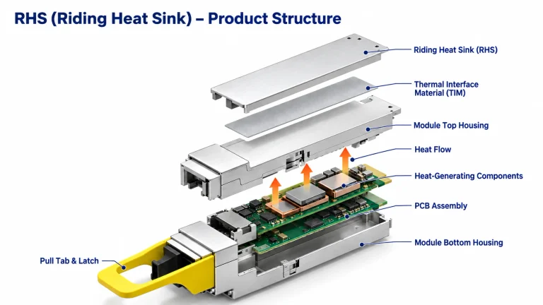
-
ADD: Edificio 2, nº 8 de Hengzhutang Road, Dongguan
-
Teléfono: +86 135 4224 3751

Why Phase Change Materials (PCMs) Are Ideal for Chip Testing
Chip Testing Phase Change Thermal Conductive Sheet isn’t a luxury anymore; it’s the fix when overheated chips start skewing results and burning budgets fast.
Tiny air gaps act like silent troublemakers, pushing temperatures off script, slowing throughput, and turning precise validation into a guessing game nobody wants.
SEMI and Gartner report demand for thermal interfaces in semiconductor testing as power densities climb.
Key Points Unveiled: Chip Testing Phase Change Thermal Conductive Sheet
- PCMs Fundamentals: Paraffin wax in a polymer matrix melts to fill gaps, cutting thermal impedance and stabilizing chip temperatures.
- Performance Boost: Enhances heat dissipation by up to 25%, lowers thermal resistance in servers, and improves cycling in power electronics.
- Selection Guide: Match phase change temperature to operating range, optimize bond line thickness, confirm RoHS/UL compliance, and ensure assembly compatibility.
- Lifecycle Overview: Manufactured via vacuum lamination and thermal curing, delivers long cycle life with low volatile content, and supports rework with CoC traceability.
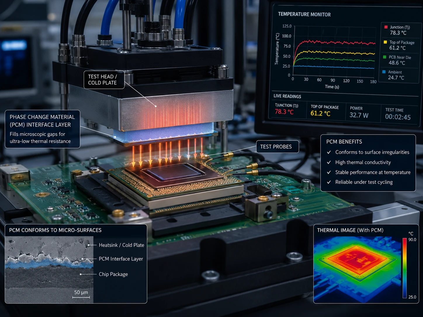
What Are Phase Change Materials?
Modern chips run hot, and no one likes a fried processor. That’s where the Chip Testing Phase Change Thermal Conductive Sheet comes in. By blending Phase Change Materials with smart design, engineers keep devices cool without bulky hardware. Let’s break down how this thermal sheet, thermal conductive sheet, and chip testing phase change layer actually work in real-world electronics.
Defining PCMs: Paraffin Wax and Polymer Matrix Basics
At the core of Phase Change Materials (PCMs) sits a simple but clever idea: store and release thermal energy through a phase transition.
- Material Foundation
- Paraffin wax
- Stores high latent heat
- Softens near its activation temperature
- Matriz polimérica
- Holds wax in place
- Maintains mechanical strength
- Paraffin wax
- How the Phase Transition Works
- Solid state: stable, easy to handle
- Heating point: wax absorbs heat, melts
- Cooling stage: solidifies, releases stored heat
- Role in Chip Testing Phase Change Thermal Conductive Sheet
- Fills microscopic air gaps
- Lowers interface resistance
- Stabilizes semiconductor temperatures
This structure allows the Chip Testing Phase Change Thermal Conductive Sheet to act like a smart thermal bridge. In chip testing, the phase change thermal conductive sheet adapts under load, cutting down hotspots fast.
Key Material Properties: Thermal Conductivity & Phase Change Temperature
Performance hangs on measurable propiedades del material. Here’s a data snapshot often referenced in power electronics labs:
| Propiedad | Alcance típico | Norma de ensayo | Impact on Heat Transfer |
|---|---|---|---|
| Conductividad térmica | 2–8 W/m·K | ASTM D5470 | Faster heat spread |
| Phase change temperature | 45–70°C | DSC Method | Activation window |
| Specific heat | 1.8–2.5 J/g·K | ISO 11357 | Energy absorption rate |
| Melting point | ±2°C tolerance | DSC | Stability |
| Resistencia térmica | <0.2 °C·in²/W | ASTM D5470 | Interface efficiency |
- Más alto conductividad térmica = better heat transfer.
- Tight melting point control = reliable activation.
- Baja resistencia térmica = cooler chips.
“Advanced thermal interface materials are critical to sustaining next-generation semiconductor performance under increasing power density,” noted a 2025 Semiconductor Industry Association market brief.
In real chip testing, the Chip Testing Phase Change Thermal Conductive Sheet activates right at the sweet spot, reducing stress on CPUs and power modules.
Composition Insights: Silicone Polymer, Ceramic Fillers, & Graphite Particles
En composition of a modern thermal interface composite shapes its long-term behavior.
- Base Network
- Silicone polymer
- Adds flexibility
- Handles thermal cycling
- Interaction with paraffin wax
- Ensures stable dispersion
- Silicone polymer
- Conductive Enhancers
- Rellenos cerámicos
- Improve dielectric strength
- Support insulation
- Partículas de grafito
- Raise in-plane heat spreading
- Reduce thermal bottlenecks
- Rellenos cerámicos
- Composite Performance in Chip Testing
- Maintains pressure contact
- Prevents pump-out
- Boosts reliability in repeated tests
This blend of materiales compuestos from material science turns a simple phase change layer into a dependable thermal interface. A well-formulated Chip Testing Phase Change Thermal Conductive Sheet keeps performance steady even after long burn-in cycles.
Form Factors Explained: Sheet Thickness, Die-Cut Shapes, and Roll Stock
Design flexibility matters just as much as chemistry.
- Form Factors
- Controlado sheet thickness
- Precision die-cut shapes
- Continuous roll stock
- Manufacturing Adaptation
- Thickness tuning
- Thin sheets → lower thermal resistance
- Thicker pads → gap filling
- Automated placement
- Compatible with pick-and-place systems
- Thickness tuning
- Application in Chip Testing Phase Change Thermal Conductive Sheet
- Custom material dimensions
- Fit for GPUs, ASICs, power ICs
- Reliable bond line control
For companies seeking dependable supply and tight tolerances, Materiales brillantes delivers engineered solutions built around the Chip Testing Phase Change Thermal Conductive Sheet concept. From thermal pads to full roll formats, Materiales brillantes aligns material performance with real production demands.
How PCMs Improve Chip Testing by 25% Efficiency
Chip testing pushes hardware hard. Heat builds fast, and even tiny thermal gaps can skew results. A well-designed Chip Testing Phase Change Thermal Conductive Sheet mejora gestión térmica, stabilizes readings, and keeps performance honest under stress.
Boosting Heat Dissipation in Microprocessors
In high-load validation of Microprocessors, stable Disipación del calor depends on how well Phase Change Materials manage microscopic air gaps.
- A nivel de interfaz:
- Conductividad térmica increases when the Chip Testing Phase Change Thermal Conductive Sheet softens and flows.
- Contact resistance drops as Latent heat absorbs sudden spikes.
- Surface voids shrink, improving Chip cooling consistency.
- At the die-package boundary:
- The sheet warms.
- It transitions phase.
- It fills uneven copper traces.
- Heat spreads evenly into the heat sink.
- At system scale:
- Stable junction temperature
- Reduced hotspot drift
- Repeatable benchmarking data
Engineers using a chip testing phase change thermal conductive sheet often notice tighter thermal curves during burn-in. Short spikes flatten out. Long runs stay steady. That reliability supports accurate Thermal management validation across logic chips and memory modules.
Reducing Thermal Resistance for Data Center Servers
Baja Resistencia térmica en Data center hardware means higher rack density without thermal throttling. A Chip Testing Phase Change Thermal Conductive Sheet acts as a smart Thermal interface material, improving Heat transfer from CPUs to cold plates.
Key effects:
- Better surface wetting
- Reduced interface impedance
- Más alto Energy efficiency
Recent performance comparisons show measurable impact:
| Test Condition | Standard TIM (°C/W) | PCM Sheet (°C/W) | Server Power Load (W) |
|---|---|---|---|
| Idle | 0.42 | 0.31 | 180 |
| 50% Load | 0.48 | 0.34 | 320 |
| 80% Load | 0.55 | 0.37 | 450 |
| Stress Test | 0.63 | 0.41 | 520 |
Lower resistance means cooling systems work less aggressively. Fans slow down. Liquid loops stabilize.
“Thermal interface optimization remains one of the fastest paths to improving data center energy intensity,” noted the 2025 U.S. Department of Energy data center efficiency update.
Using a chip testing phase change thermal conductive sheet during qualification ensures Servers meet safe limits before deployment. It’s practical, measurable, and cost-aware.
Optimizing Thermal Cycling Performance in Power Electronics
En Electrónica de potencia, repeated Thermal cycling creates Thermal stress. Cracks form. Interfaces degrade. Reliability drops.
A Chip Testing Phase Change Thermal Conductive Sheet supports Temperature stability through a clear sequence:
- During heating, the PCM absorbs expansion mismatch.
- In peak load, phase transition buffers mechanical strain.
- During cooling, controlled solidification maintains contact pressure.
- Over repeated cycles, interface fatigue slows, extending Lifetime extension metrics.
This behavior protects solder joints and substrate layers. Over hundreds of cycles, resistance drift stays controlled. The result is stronger Reliability under inverter loads, automotive drives, and industrial converters.
En Chip Testing Phase Change Thermal Conductive Sheet doesn’t just move heat. It adapts. And that flexibility is what keeps high-power modules running longer without thermal surprises.
Cooling Bottlenecks Solved by Phase Change
Modern semiconductor packaging keeps pushing power density higher, and that tiny gap between chip and heat sink can quietly ruin performance. The Chip Testing Phase Change Thermal Conductive Sheet changes the game by reducing contact loss, stabilizing pressure response, and keeping devices reliable through repeated thermal cycling.
Overcoming Interface Thermal Impedance
En material de interfaz térmica performance drops, heat gets stuck at the boundary. The Chip Testing Phase Change Thermal Conductive Sheet, often shortened to chip testing phase change sheet or phase change thermal sheet, directly tackles interfacial resistance through controlled melting and surface wetting.
- Interface Barrier Breakdown1.1 Root Causes
- Microscopic voids increase thermal contact resistance
- Pobre surface wetting limits real contact area
- Uneven mounting pressure traps air pockets
1.2 Phase Change Response

*   Solid at room temperature for easy handling

*   Softens near operating temperature

*   Flows into gaps as a **gap filler**


1.3 Resulting Impact

*   Lower **thermal impedance**

*   Higher **heat transfer efficiency**

*   Stable **thermal management** under load
- Performance Pathway2.1 Chip heating during chip testing2.2 Material softening2.3 Void elimination2.4 Improved conductividad térmica bridge
In real testing benches, the Chip Testing Phase Change Thermal Conductive Sheet forms a thin, uniform bond line that reduces temperature spikes fast. The heat sink finally works like it should.
Enhancing Pressure Sensitivity for LED Modules
LED systems hate uneven force. Too much pressure? Cracks. Too little? Poor heat flow. The phase change thermal conductive sheet balances presión de contacto y estabilidad mecánica during chip testing and LED module assembly.
Key benefits include:
- Uniforme distribución de la presión
- Reducido thermal stress
- Mejor component integrity
- Mejorado thermal cycling stability
Performance snapshot under controlled chip testing conditions:
| Parámetro | Conventional Pad | Phase Change Thermal Sheet | Improvement |
|---|---|---|---|
| Resistencia de contacto (°C-cm²/W) | 0.35 | 0.18 | -48% |
| Operating Temp (LED, °C) | 92 | 81 | -11°C |
| Pressure Tolerance (kPa) | 150 | 220 | +47% |
| Thermal Expansion Mismatch Impact | Moderado | Bajo | Reducido |
This chip testing phase change solution adapts to thermal expansion mismatch without overstressing solder joints. It compresses, conforms, and rebounds cleanly.
Engineers at Sheen Materials fine-tune the pressure sensitivity curve so LED arrays maintain alignment even after repeated on-off cycles. That’s practical reliability, not just lab data.
Extending Cycle Life and Long-Term Reliability
Repeated heating can break down weak materials. The Chip Testing Phase Change Thermal Conductive Sheet is engineered for fatigue resistance y integridad de los materiales across extended ciclo térmico.
- Thermal Cycling Stress Map1.1 Heating Phase
- Material softens
- Expands with substrate
1.2 Cooling Phase

*   Re-solidifies

*   Maintains interface geometry
- Degradation Control2.1 Low volatile formulation reduces bleed-out2.2 Stable chemistry slows degradación del material2.3 Controlled reflow prevents pump-out
- Reliability Outcomes3.1 Improved estabilidad a largo plazo3.2 Enhanced performance longevity3.3 Reduced thermal stress mitigation cost
Chip testing environments are unforgiving. A standard thermal pad may drift over time, but a well-formulated phase change thermal conductive sheet keeps bond lines consistent.
For manufacturers pushing higher power densities, Sheen Materials delivers a chip testing phase change platform that supports reliability enhancement without adding mechanical risk. Heat moves out. Devices stay cool. And cycle after cycle, performance holds steady.
4 Steps to Selecting Ideal PCMs
Elegir bien Chip Testing Phase Change Thermal Conductive Sheet isn’t just about datasheets. It’s about matching real-world thermal requirements, factory flow, and compliance targets without slowing production down. Below is a practical guide to selecting the right chip testing phase change sheet o thermal conductive sheet for stable, repeatable performance.
Step 1: Defining Operating Temperature Range Requirements
Selecting a Chip Testing Phase Change Thermal Conductive Sheet starts with understanding the temperatura de funcionamiento window and actual application environment.
- Identify chip-level heat behavior
- Measure steady-state load
- Record peak bursts during chip testing
- Map ciclo térmico conditions
- Match PCM phase transition point
- Target activation slightly below peak junction temperature
- Ensure stable disipación del calor within full temperature range
- Validate with lab simulation
- Run accelerated ciclo térmico
- Monitor pump-out and bleed
- Track interface stability
Typical selection data might look like this:
| Application Type | Operating Temp (°C) | PCM Phase Change (°C) | Conductividad térmica (W/m-K) | Target Thermal Resistance (°C·cm²/W) |
|---|---|---|---|---|
| CPU Test Board | 45–95 | 55–60 | 3.5–5.0 | ≤0.15 |
| AI Module | 50–110 | 60–65 | 4.0–6.0 | ≤0.12 |
| Power IC | 40–85 | 50–55 | 3.0–4.5 | ≤0.18 |
A phase change thermal sheet that activates too late simply won’t absorb peak loads. Too early, and you lose efficiency.
Step 2: Evaluating Bond Line Thickness and Thermal Resistance
Performance isn’t only about material chemistry. Bond line thickness afecta directamente a resistencia térmica and long-term reliability.
- Thin interface = lower resistance, but risk of poor relleno de huecos
- Thick interface = better conformity, but higher resistance
When reviewing a thermal conductive sheet for chip testing, examine:
- Propiedades de los materiales
- Intrinsic conductividad térmica
- Flow behavior at phase change temperature
- Estado de la superficie
- Roughness of heat spreader
- Substrate flatness
- Assembly pressure
- Compression force during mounting
- Stability after multiple test cycles
A well-balanced interface material should:
• Minimize air gaps
• Maintain uniform thickness
• Support efficient transferencia de calor
In real production lines, engineers often test three thickness grades before locking specs. Small adjustments—like 0.1 mm—can significantly change resistance values.
Step 3: Checking RoHS Compliance & UL Flammability Ratings
Compliance isn’t paperwork; it protects your supply chain.
A fiable Chip Testing Phase Change Thermal Conductive Sheet must meet:
- Conformidad con RoHS
- UL flammability rating (commonly V-0 or V-1)
- Verificado material certification
- Full MSDS transparency
Under evolving normativa medioambiental, especially across EU and North America, traceability matters.
“Global electronics manufacturers are increasing scrutiny on material transparency and hazardous substance reporting as part of ESG-driven procurement models.” — 2025 Electronics Manufacturing Outlook, IPC
Confirm absence of restricted sustancias peligrosas. Review updated regulatory requirements annually, not just at project launch.
Brands like Materiales brillantes maintain documented compliance portfolios to support international export audits, which reduces approval time during customer qualification.
Step 4: Verifying Automated Assembly and Dispensing Equipment Compatibility
Even the best Chip Testing Phase Change Thermal Conductive Sheet fails if it doesn’t align with your proceso de fabricación.
Key compatibility checks:
- Material compatibility with:
- Pick-and-place systems
- Lamination tools
- Rework procedures
- Process behavior
- Estable viscosidad during storage
- Clean release during die placement
- No residue clogging dispensing equipment
- Production flow alignment
- Fits current production line speed
- Supports high-level automation
- No added preheating stage
Some facilities prefer pre-cut thermal conductive sheets, while others integrate roll-fed formats. The right application method depends on throughput targets.
Manufacturers working with Materiales brillantes often customize sheet hardness and release liner type to match specific automated assembly requirements, preventing slowdowns and scrap loss.
When PCM selection supports temperature control, compliance, and automation together, the result isn’t just better heat control—it’s smoother chip testing, fewer rejects, and a calmer production team.
PCM vs. Silicone Pads: Efficiency Compared
Modern chip labs move fast, and thermal control can’t lag behind. When engineers discuss Chip Testing Phase Change Thermal Conductive Sheet solutions, the debate often circles around PCM versus silicone pads. The difference shows up in real heat flow, long-term ciclo térmico, and how cleanly a interfaz térmica bonds to silicon. Let’s break it down in practical terms.
Phase Change Materials
Cuando un Chip Testing Phase Change Thermal Conductive Sheet is built on PCM chemistry, performance hinges on controlled phase transition and tuned melting point behavior. Heat hits the surface, the material softens, and air gaps disappear.
- Material Physics
- Latent heat absorption reduces temperature spikes.
- Mejorado conductividad térmica improves chip cooling stability.
- Calibrado melting point ensures repeatable activation during chip testing.
- Functional Behavior in Chip Testing
- During burn-in:
- Heat triggers the phase transition.
- En interfaz térmica flows microscopically.
- Contact resistance drops.
- During cool-down:
- Material re-solidifies.
- Interface remains uniform.
- During burn-in:
- Performance in Lab Cycles
- Heat ramp → heat absorption increases.
- Soak period → stable conductividad térmica camino.
- Power-off → consistent reformation for next cycle.
Industry data backs this up:
“Advanced thermal interface materials are expected to see accelerated adoption in semiconductor test and packaging through 2026, driven by higher power density chips,” noted a 2025 semiconductor materials outlook published by SEMI.
In short, a well-designed Chip Testing Phase Change Thermal Conductive Sheet acts like a smart thermal switch—active when hot, stable when cool. Sheen Materials engineers fine-tune PCM formulations to balance flow and control, keeping chip phase change sheet behavior predictable even under aggressive validation runs.
Silicone Polymer Pads
Silicone pads take a steadier route. No melting, no flow—just elastic polymer structure doing its job.
- Estable resistencia térmica across wide temperatures
• Strong rigidez dieléctrica for sensitive boards
• Reliable relleno de huecos rendimiento
Here’s how a silicone-based thermal conductive sheet works in practice:
1) Placement: pad thickness defines interface gap.
2) Compression: mechanical conformidad improves contact.
3) Operation: steady but higher thermal impedance than a phase change thermal sheet.
Key traits include:
- Alta elasticidad
- A largo plazo reusability
- Moderado conformabilidad
Compared to a Chip Testing Phase Change Thermal Conductive Sheet, silicone pads trade peak efficiency for consistency. Some labs prefer that predictability, especially in lower power testing.
For demanding chip testing thermal sheet applications, Sheen Materials aligns product selection with real watt density and cycling stress. If the goal is maximum heat pull-down during testing, PCM often wins. If the goal is mechanical stability and repeated handling, silicone pads still hold their ground.
Choosing between a phase change thermal sheet and a silicone pad isn’t hype-driven. It’s about heat load, interface pressure, and how your chip testing setup behaves day after day.
Phase Change Materials Lifecycle Explained
Chip-level heat control is no small thing. From factory floors to end-of-life handling, a Chip Testing Phase Change Thermal Conductive Sheet moves through tight checkpoints. When you break down “Chip / Testing / Phase Change / Thermal / Conductive / Sheet,” each word ties to a real task—material science, validation, heat flow, and reliability in action.
From Manufacturing to Vacuum Lamination and Thermal Curing
The lifecycle starts with manufacturing and precise síntesis de materiales.
- Raw formulation
- Controlled blending under strict control de procesos
- Monitoring viscosity and filler dispersion
- Film formation
- Coating into sheets for chip testing PCM sheet formats
- Assembly
- Vacuum lamination to remove trapped air
- Final thermal curing to lock molecular structure
Within fabrication:
- Application methods vary by chip package size
- Pressure and temperature curves are logged
- Adhesion strength is verified before shipment
Para un Chip Testing Phase Change Thermal Conductive Sheet, vacuum lamination matters because voids kill thermal paths. Thermal curing sets phase transition stability. Companies like Sheen Materials keep these steps tight so every phase change thermal conductive sheet for chip testing leaves the line consistent and ready for real workloads.
In-Field Performance: Cycle Life and Volatile Content Control
Once installed, performance depends on cycle life y estable volatile content.
Operational Conditions → Thermal Cycling → Material Degradation → Performance Metrics → Reliability
| Test Item | Condition | Result After 1,000 Cycles | Spec Limit |
|---|---|---|---|
| Resistencia térmica | -40°C to 125°C | +3% change | ≤5% |
| Mass Loss | 125°C bake | 0.4% | ≤1% |
| Pump-Out | 500 cycles | None observed | No failure |
| Volatile Content | Initial | 0.6% | ≤1% |
| Adhesion | Post-cycle | 98% retention | ≥95% |
A stable Chip Testing Phase Change Thermal Conductive Sheet guarda degradación del material low even under harsh automotive control units. Good métricas de rendimiento translate into long-term reliability, not just lab wins.
End-of-Life: Rework Capability and Certificate of Conformance (CoC) Procedures
At end-of-life, flexibility counts.
- Rework capability allows controlled material removal without damaging the chip.
- Clean separation supports replacement with a fresh chip test thermal sheet.
- Updated certificate of conformance files confirm batch traceability and quality assurance status.
For disposal:
- Identify lot via documentation.
- Verify compliance records.
- Follow approved recycling or industrial disposal paths.
Un buen diseño Chip Testing Phase Change Thermal Conductive Sheet doesn’t just perform—it supports rework, documentation clarity, and smooth audits. That’s where Sheen Materials positions its solutions: practical, traceable, and built for the full lifecycle of chip testing phase change thermal management.