-
ADD: Building 2, No. 8 Hengzhutang Road, Dongguan
-
Telefone: +86 135 4224 3751

TIM1 vs. TIM2 vs. TIM1.5: How to Select Thermal Interface Materials for AI Chips and HPC Cooling
Why TIM Selection Matters in AI and HPC Thermal Design?
As AI servers, GPU accelerators, high-performance computing (HPC) systems, and advanced semiconductor packages continue to increase in power density, thermal design has become a critical factor in system performance, reliability, and service life.
In many systems, the challenge is not only how powerful the heat sink, cold plate, or liquid cooling loop is. A major part of the thermal bottleneck occurs at the interfaces between solid surfaces: the die, integrated heat spreader (IHS), package lid, cold plate, heat sink, power module baseplate, or metal enclosure.
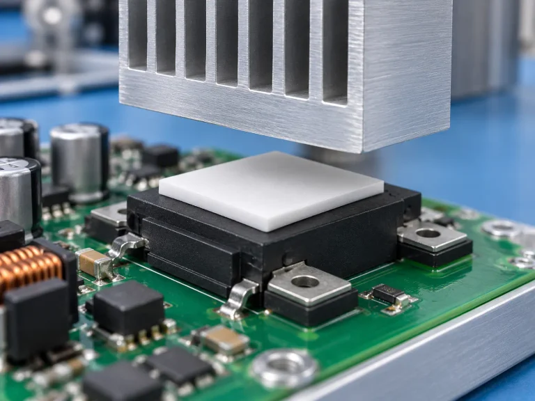
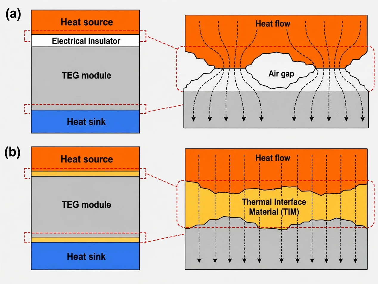
Thermal interface materials (TIMs) are used to fill microscopic air gaps between these surfaces. By replacing trapped air with a more conductive material, TIMs help reduce interface thermal resistance and create a more reliable heat transfer path.
For engineers working on AI chips, HPC systems, power electronics, optical modules, and high-density computing platforms, understanding the differences between TIM1, TIM2, and TIM1.5 is essential for selecting the right material and validating it under real operating conditions.
Why Does AI Chip Cooling Increasingly Depend on TIMs?
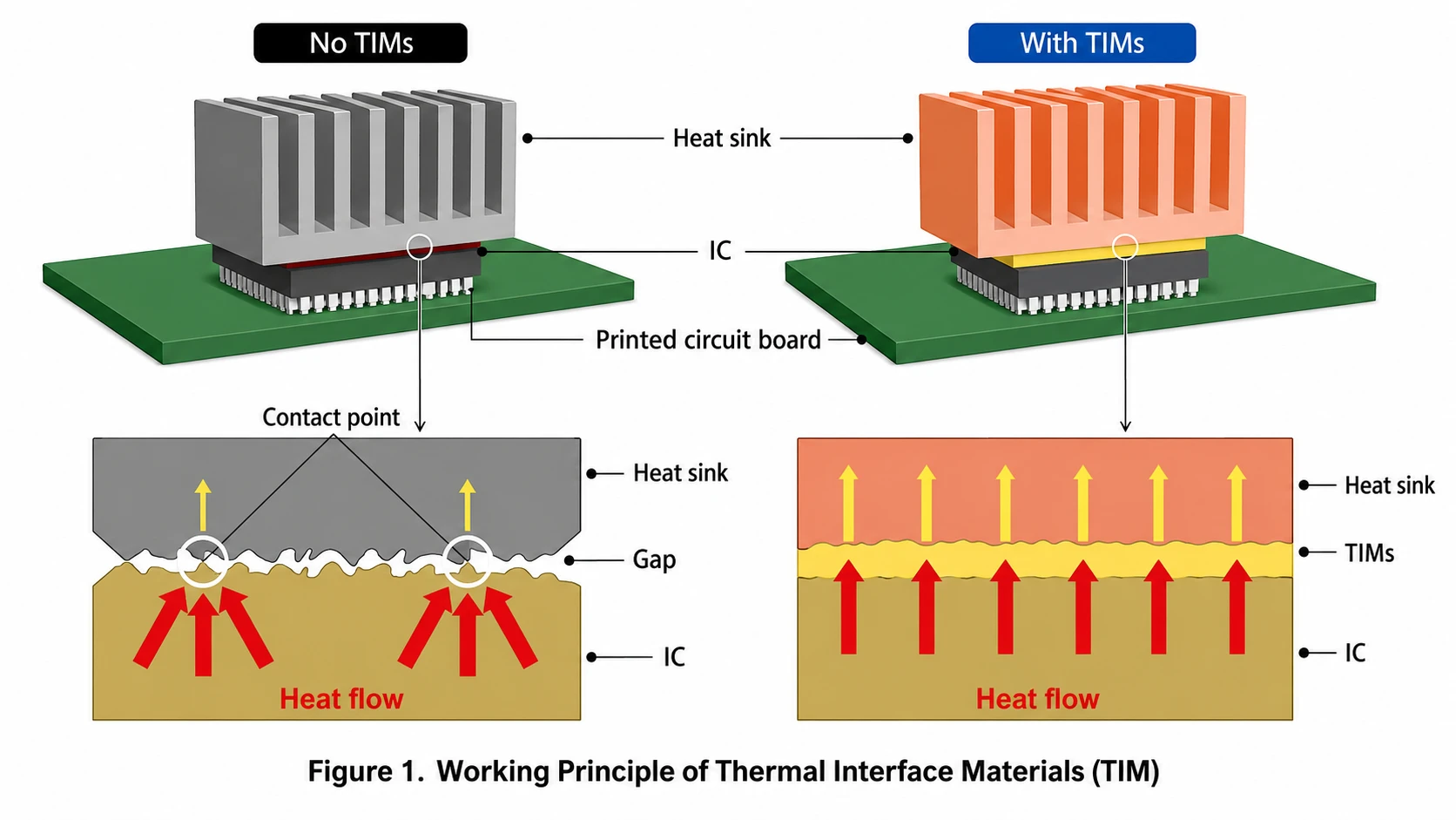
When two solid surfaces are placed together, they never make perfect contact. Even highly polished surfaces contain microscopic roughness, waviness, and uneven contact points. Under clamping pressure, the surfaces touch only at limited points, leaving many tiny voids between them.
Those voids are usually filled with air. At room temperature, air has a very low thermal conductivity, about 0.026 W/(m·K), which makes it a poor heat transfer medium. In high-power devices, these air pockets can significantly increase interface thermal resistance and raise junction temperature.
AI processors, GPUs, ASICs, and HBM-adjacent components generate concentrated heat in a small package area. As a result, the thermal path from the silicon die to the cooling structure must be carefully controlled. A suitable TIM can help fill surface gaps, improve wetting, reduce contact resistance, and maintain stable heat transfer over time.
What TIMs are designed to do
- Fill microscopic gaps between two mating surfaces.
- Displace air from the thermal interface.
- Improve the contact area between the device and the heat spreader, cold plate, or heat sink.
- Reduce interface thermal resistance.
- Maintain stable performance under pressure, temperature cycling, and long-term operation.
What Is a TIM? It Solves an Interface Thermal Resistance Problem
A thermal interface material is not a replacement for the cooling system itself. Instead, it is the material that allows the cooling system to work more effectively by improving the interface between the two contact surfaces.
In practical thermal design, engineers should not evaluate a TIM solely by its thermal conductivity. The final thermal performance is influenced by the material thickness, bond line thickness (BLT), contact pressure, surface roughness, compression behavior, pump-out resistance, aging stability, and electrical requirements.
Polymer-based TIMs are widely used because they can be formulated to provide softness, conformability, adhesion, reworkability, and mechanical compliance. Since most polymers have low intrinsic thermal conductivity, thermally conductive fillers such as alumina, boron nitride, aluminum nitride, graphite, graphene, metal powders, or hybrid filler systems are added to improve heat transfer.
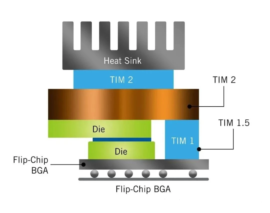
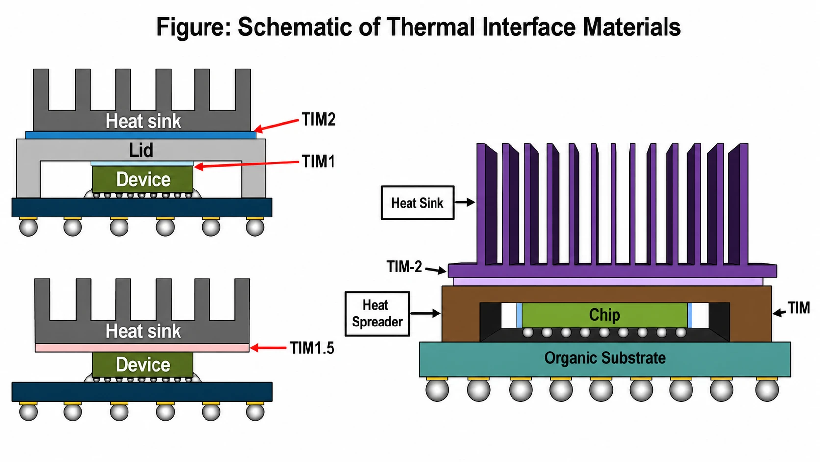
Where Are TIM1, TIM2, and TIM1.5 Used?
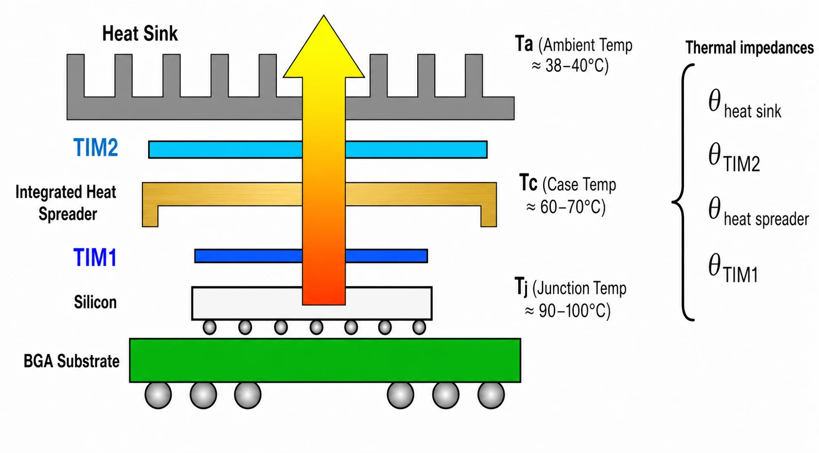
TIM1, TIM2, and TIM1.5 describe the location of the thermal interface in the package or system-level heat path. Because each location has different mechanical and thermal requirements, the same material should not be
| TIM Type | Typical Location | Main Engineering Challenge | Common Material Options | Selection Priority |
| TIM1 | Between the silicon die and the integrated heat spreader (IHS) | Very high heat flux, thin interface, strict reliability requirements | Thermal adhesive, indium preform, phase change material | Low thermal resistance, pump-out control, aging stability |
| TIM2 | Between the IHS and the heat sink or cold plate | Larger contact area, variable assembly pressure, mechanical tolerance stack-up | Thermal grease, thermal pad, gap filler, phase change material | Thickness fit, compression, reworkability |
| Low pressure, low thermal resistance, die protection, and reliability | Between a bare die and a heat sink or cold plate in lidless packages | Protecting the bare die while maintaining efficient heat transfer | High-performance grease, phase change material, liquid metal, compliant pad | Low pressure, low thermal resistance, die protection, reliability |
evaluated using one universal standard.
TIM1 vs. TIM2 vs. TIM1.5: Key Selection Differences
The key difference is not simply material type. It is the mechanical and thermal environment in which the TIM must operate.
| Selection Factor | TIM1 | TIM2 | TIM1.5 |
| Percurso térmico | Die to IHS | IHS to heat sink or cold plate | Bare die to heat sink or cold plate |
| Typical interface thickness | Very thin | Thin to moderate, depending on assembly gap | Thin, but must protect fragile die surfaces |
| Pressure sensitivity | Elevado | Medium to high | Muito elevado |
| Reliability concern | Pump-out, dry-out, aging, voiding | Compression set, reworkability, thermal cycling | Die cracking risk, pressure distribution, pump-out |
| Best evaluation method | Package-level thermal and reliability testing | System-level thermal testing under real clamp load | Die cracking risk, pressure distribution, and pump-out |
What Parameters Matter Most When Selecting TIMs for AI and HPC?
In AI servers, HPC clusters, GPU modules, and high-power chip packages, a TIM must maintain a low-resistance heat path under real assembly conditions. The following parameters should be evaluated together, rather than in isolation.
1. Thermal Conductivity
Thermal conductivity, measured in W/(m·K), describes the material’s ability to conduct heat. It is usually the first value engineers check when comparing TIMs.
However, higher thermal conductivity does not automatically mean better system-level cooling. The final result also depends on thickness, contact pressure, surface roughness, wetting, compression behavior, and long-term stability.
Use thermal conductivity as an initial screening metric, not as the final selection criterion.
2. Thermal Resistance
Thermal resistance is often more relevant than thermal conductivity because it reflects how much the material resists heat flow across the actual interface.
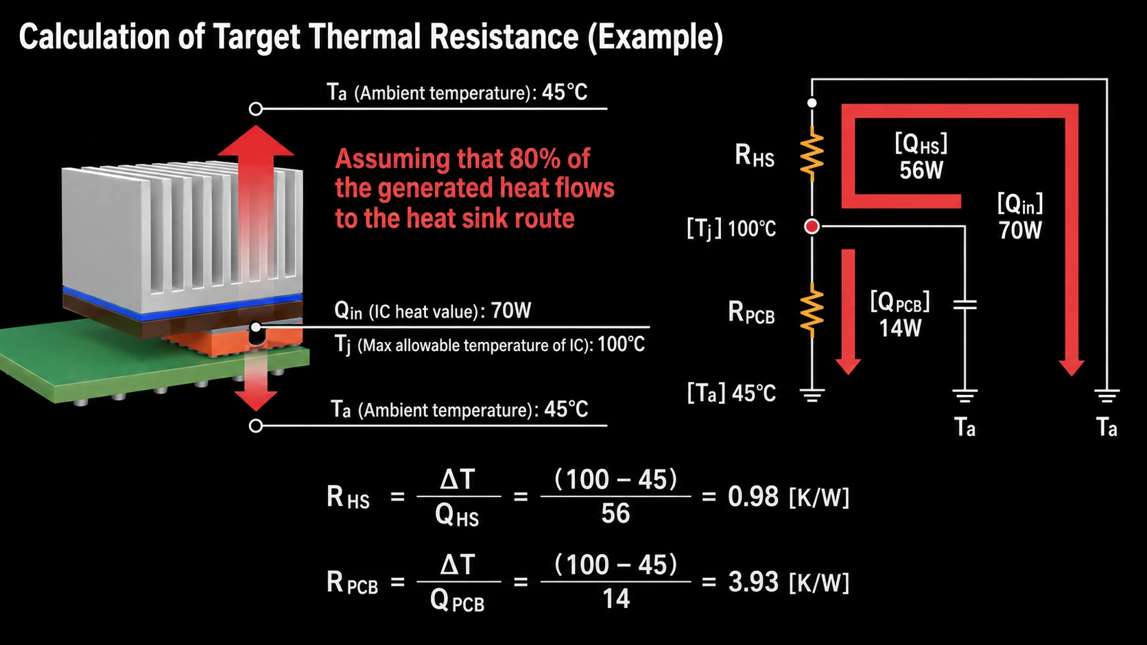
For AI chips, GPUs, and high-power modules, low thermal resistance helps reduce the temperature rise across the interface. Engineers should evaluate thermal resistance at the expected pressure, thickness, and operating temperature.
For TIM1.5 applications, interface thermal resistance is especially critical because the material must transfer heat efficiently while limiting mechanical stress on the bare die.
3. Bond Line Thickness (BLT)
Bond line thickness is the actual thickness of the TIM layer after assembly and compression. BLT directly affects the thermal path length.
A thicker TIM layer usually increases thermal resistance. A layer that is too thin may not fill surface gaps completely, leaving trapped air and local contact failure.
In TIM1 applications, BLT is typically very thin. In TIM2 applications, BLT must accommodate assembly tolerances. In TIM1.5 applications, BLT must balance low resistance with die protection.
4. Compression and Conformability
AI and HPC systems often contain complex tolerance stacks between the package, IHS, cold plate, heat sink, and mechanical frame. A TIM must be soft enough to conform to surface irregularities and fill gaps.
If the material is too hard, it may not wet the interface properly. If it is too soft, it may deform, shift, or lose thickness stability during long-term operation.
Compression behavior should be checked under the expected assembly load and after thermal cycling.
5. Pump-Out Resistance
Pump-out occurs when a TIM gradually moves out of the interface due to temperature cycling, mechanical stress, or thermal expansion mismatch.
In high-load AI processors and GPU modules, frequent temperature changes can make pump-out a serious reliability risk. As material leaves the interface, the effective contact area decreases, and thermal resistance rises.
Greases, low-viscosity materials, and some phase change materials should be evaluated carefully for pump-out performance.
6. Outgassing and Bleeding
Outgassing refers to volatile components released from a material under heat or vacuum conditions. Bleeding refers to the migration of oils or low-molecular-weight components from the TIM.
For optical modules, sensors, high-speed communication equipment, and precision electronics, contamination can affect device stability, optical performance, or long-term reliability.
Low-outgassing and low-bleeding materials are important in applications where cleanliness and interface stability matter.
7. Electrical Insulation
Some TIM locations require both heat transfer and electrical isolation. This is common in power electronics, MOSFETs, IGBTs, SiC modules, power supplies, GPU boards, and high-voltage electronic systems.
Key electrical parameters include volume resistivity, dielectric strength, breakdown voltage, dielectric constant, dielectric loss, and flame-retardant performance.
Metal-based thermal solutions can conduct heat well, but they may introduce short-circuit risk. For electrically sensitive applications, ceramic-filled pads, boron nitride thermal pads, and thermally conductive insulation films are often more suitable.
8. Aging Stability
AI servers and HPC systems may operate continuously for long periods. A TIM must remain stable under high temperature, pressure, and thermal cycling.
Important aging indicators include thermal resistance drift, hardening, cracking, powdering, oil bleeding, outgassing, compression set, and electrical insulation retention.
Long-term stability directly affects system reliability, maintenance cost, and thermal safety margin.
9. Reworkability
Servers, GPU modules, and high-value electronics may require maintenance, module replacement, or cooling system reassembly. TIM reworkability affects production efficiency and field service cost.
Thermal greases and pads are generally easier to remove and replace. Some phase change materials require process-specific evaluation. Liquid metals and cured adhesives can be more difficult to rework.
If the system requires future serviceability, reworkability should be considered during material selection.
10. Application Fit
The final question is not “Which TIM has the highest thermal conductivity?” It is “Which TIM best fits this interface, pressure range, reliability target, and heat path?”
TIM1, TIM2, and TIM1.5 should not be selected using the same assumptions. Each position requires a different balance of thermal resistance, thickness, pressure, compliance, electrical requirements, and durability.
For AI and HPC systems, the best TIM solution is the one that maintains stable contact and low interface resistance throughout the product life cycle.
| Application Position | Main Challenge | Selection Focus |
| TIM1: Die to IHS | Very high heat flux and very thin interface | Low thermal resistance, low pump-out, high reliability |
| TIM2: IHS to heat sink / cold plate | Assembly tolerance and larger contact area | Thickness fit, compression, reworkability |
| TIM1.5: Bare die to heat sink | Bare die protection and low-stress heat transfer | Low pressure, low thermal resistance, mechanical cushioning |
| GPU / AI accelerator | High power and long operating hours | Thermal resistance stability and aging performance |
| Optical module / high-speed communication | Small space and high local heat flux | Low outgassing, insulation, dimensional stability |
| Power module / power supply | Heat transfer plus electrical isolation | Power module/power supply |
throughout the product life cycle.
Material Recommendations for Different Heat Paths
Different heat paths require different material directions. The following table is intended as a selection framework, not as a fixed formula. Final material choice should always be validated with the actual device structure and operating conditions.
| Heat Path / Interface | Engineering Problem | Material Direction to Evaluate |
| Chip / IHS interface | Extremely low thermal resistance and thin bond line | Massa térmica, phase change material, indium preform |
| IHS / heat sink or cold plate | Assembly tolerance and large contact area | Thermal pad, thermal gel, thermal grease |
| Power device / heat sink | Heat transfer plus electrical isolation | Compact space, high heat flux, and cleanliness requirements |
| Optical module / DSP | Compact space, high heat flux and cleanliness requirements | High-conductivity pad, silicone-free thermal pad, low-outgassing material |
| Power module / MOSFET | Compression fit and long-term stability | Gap filler, thermal pad, electrically insulating material |
From Material Screening to Reliability Validation: How Materiais de brilho Supports TIM Selection
In AI servers, HPC systems, GPU accelerators, optical modules, and high-power electronic devices, TIM selection is not simply a matter of choosing the highest thermal conductivity grade. Package structure, thermal path, interface gap, assembly pressure, and reliability targets all affect the final result.
Materiais de brilho supports engineering teams by helping them move from datasheet comparison to application-based validation. The goal is to identify a TIM solution that fits the real heat path, mechanical design, and reliability requirements of the target device.
1. Identify the TIM location in the heat path
At the beginning of a project, engineers need to define where the TIM is used. TIM1, TIM2, and TIM1.5 have different interface structures and should be evaluated differently.
| Low outgassing, dimensional stability, and high heat flux support | Typical Interface | Sheen Materials Support Focus |
| TIM1 | Die to IHS | Low thermal resistance, thin bond line, interface stability |
| TIM2 | IHS to heat sink or cold plate | Thickness fit, compression behavior, reworkability |
| TIM1.5 | Bare die to heat sink or cold plate | Low pressure, low thermal resistance, die protection |
| Power device interface | MOSFET, IGBT or SiC module to heat spreading structure | Thermal conductivity, electrical insulation and long-term reliability |
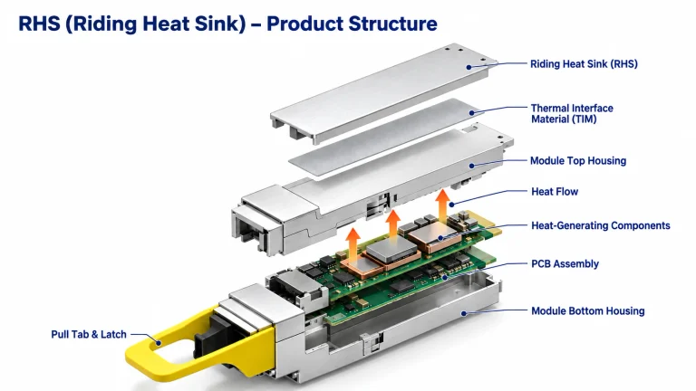
| Optical module interface | DSP, driver, TIA, housing or heat spreader | Low outgassing, dimensional stability and high heat flux support |
2. Screen materials based on operating conditions
Different applications place different demands on TIMs. Materiais de brilho can help evaluate material directions based on power level, gap size, pressure range, operating temperature, electrical requirements, and reliability targets.
| Aplicação | Common Engineering Concern | Material Direction to Consider |
| AI server / GPU module | High power, long operating time, strict thermal resistance target | High-conductivity pad, thermal gel, phase change material |
| HPC cold plate system | Large IHS-to-cold-plate area and uneven pressure distribution | Low-resistance TIM, compressible thermal interface material |
| Optical module | Small space, high heat flux and contamination sensitivity | Low-outgassing pad, silicone-free thermal material |
| Power module | Localized heat generation and electrical safety requirements | Insulating thermal sheet, boron nitride thermal pad |
| Communication equipment | Continuous operation and frequent temperature cycling | Aging-stable pad or gap filler |
| Eletrónica automóvel | High temperature, vibration and reliability requirements | High temperature, vibration, and reliability requirements |
3. Evaluate the key engineering parameters
After the initial material direction is defined, engineers should evaluate the parameters that influence real system performance.
| Evaluation Parameter | Porque é que é importante |
| Condutividade térmica | Screens the basic heat transfer capability of the material |
| Resistência térmica | Better reflects actual interface cooling performance |
| Bond line thickness | Affects the real heat path and total interface resistance |
| Compression deflection | Determines whether the material can handle assembly tolerance |
| Resistência dieléctrica | Determines suitability for high-voltage or electrically isolated applications |
| Outgassing / bleeding | Affects optical modules, sensors and precision electronics |
| Aging performance | Indicates stability under long-term high-temperature operation |
| Reworkability | Affects optical modules, sensors, and precision electronics |
4. Validate with samples under real conditions
A datasheet value does not always predict system-level performance. Before qualification, the material should be tested under the expected pressure, gap, temperature range, and reliability conditions.
| Validation Item | Purpose |
| Thickness and compression test | Confirm fit with the actual assembly gap |
| Thermal resistance test | Verify performance under target pressure and thickness |
| High-temperature aging test | Evaluate thermal performance drift over time |
| Thermal cycling test | Check pump-out, cracking, loss of contact or interface failure |
| Electrical insulation test | Confirm compliance with electrical safety requirements |
| Outgassing / bleeding evaluation | Assess suitability for optical modules, sensors and precision electronics |
| Assembly and rework test | Confirm production, service and replacement feasibility |
5. Optimize the material solution based on test feedback
- If thermal resistance is too high, adjust thermal conductivity grade, thickness, pressure, or contact design.
- If assembly pressure is too high, evaluate a softer or lower-stress material.
- If contamination risk exists, consider a low-outgassing or silicone-free material direction.
- If electrical isolation is required, evaluate ceramic-filled pads, boron nitride thermal pads, or thermally conductive insulation films.
- If maintenance is required, consider reworkability and residue after disassembly.
6. Connect application guidance with product specifications
For engineering teams that are still defining the thermal path, Sheen Materials recommends starting with the application, interface location, pressure conditions, and reliability targets.
For projects already moving into material screening or sample validation, engineers can review the Sheen Thermal product specification pages para almofadas térmicas, thermal gels, thermal greases, phase change materials, boron nitride thermal pads, and thermally conductive insulation films.
In AI and HPC thermal design, TIM selection should move beyond a single thermal conductivity number. The right material must match the actual interface location, bond line thickness, assembly pressure, reliability target, and electrical requirements.
TIM1, TIM2, and TIM1.5 each serve a different role in the heat path. By evaluating thermal resistance, compression behavior, pump-out, outgassing, dielectric properties, aging stability, and reworkability, engineers can build a more reliable thermal management strategy for high-power electronics.
Sheen Materials can support engineering teams through application analysis, material screening, sample testing, and reliability validation, helping customers build stable thermal solutions for AI servers, HPC systems, optical modules, communication equipment, power modules, and other high-power electronic applications.
1. Top Materials Used in a Battery Management System: Thermal Pad Design
2. Thermal Pad for Network Switch vs. Paste: Which One Wins?
3. What Is Thermal Insulated? Complete Guide for 2026 Buyers
4. Porquê escolher placas de isolamento de elevada condutividade térmica para os seus projectos