-
ADD: Building 2, No. 8 Hengzhutang Road, Dongguan
-
Phone: +86 135 4224 3751

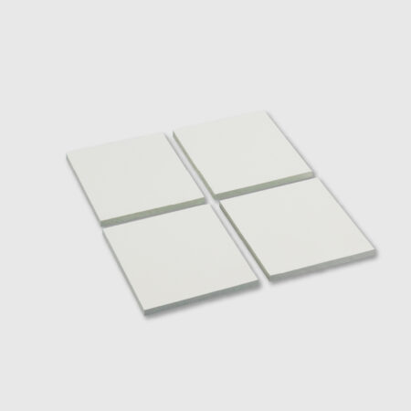


BSF1600 Boron Nitride-Filled Electrically Insulating Thermal Interface Pad — 16 W/m·K
Thin hBN-filled silicone thermal pad for IGBT, SiC/GaN power modules, inverters, RF equipment, and AI server power systems.
Key Benefits
- High thermal conductivity for faster heat transfer away from MOSFETs, IGBTs, and other high-power hot spots
- Full electrical insulation for high-voltage assemblies that still require efficient thermal conduction
- Low dielectric constant and low dielectric loss for high-frequency and EMI-sensitive applications
- Soft, flexible contact with high rebound performance for stable interface fitting
- Reliable flame-retardant and aging-resistant behavior for harsh operating conditions
- Compliant with RoHS 2.0, halogen-free, and REACH requirements
SF1600-BN Series
SF1600 Boron Nitride Thermal Pad Series
16 W/m·K Electrically Insulating Thermal Pads for High-Voltage, High-Frequency, and High-Power Electronics
The SF1600-BN series consists of flexible thermal interface pads formulated with hexagonal boron nitride (h-BN) as the thermally conductive filler and silicone rubber as the base material. The series combines high thermal conductivity, electrical insulation, low dielectric characteristics, and conformability to transfer heat from MOSFETs, IGBTs, AI chips, optical modules, and other heat-generating components to a heat sink, housing, or cold plate.
Seven current datasheet models cover nominal thicknesses from 0.3 mm to 3.0 mm. Each model retains 16 W/m·K thermal conductivity, while thermal resistance, AC breakdown voltage, and rebound rate vary by thickness. This lets engineers select the right balance of gap filling, insulation, and heat-transfer performance for the assembly.
7 Standard Models
0.3-3.0 mm Datasheet Models
16 W/m·K
Up to ≥12 kV AC
UL94 V-0
0.3-3.0 mm Datasheet Models
16 W/m·K
Up to ≥12 kV AC
UL94 V-0
Technical Information
Thickness-Specific Data
SF1600-BN Model Comparison
Use this table to compare the seven current standard datasheet models. Thermal resistance is measured at 40 psi according to ASTM D5470.
| Model | Nominal Thickness | Thermal Resistance °C·cm²/W @ 40 psi | Breakdown Voltage kV AC | Rebound Rate | Datasheet |
|---|---|---|---|---|---|
| SF1600-BN-03 | 0.3 mm | ≤0.3 | ≥4.0 | ≥90% | |
| SF1600-BN-05 | 0.5 mm | ≤0.5 | ≥5.0 | ≥80% | |
| SF1600-BN-07 | 0.7 mm | ≤0.7 | ≥6.0 | ≥70% | |
| SF1600-BN-10 | 1.0 mm | ≤0.8 | ≥10.0 | ≥70% | |
| SF1600-BN-15 | 1.5 mm | ≤1.1 | ≥12.0 | ≥60% | |
| SF1600-BN-20 | 2.0 mm | ≤1.4 | ≥12.0 | ≥60% | |
| SF1600-BN-30 | 3.0 mm | ≤1.7 | ≥12.0 | ≥60% |
Engineering note: The listed thermal resistance, breakdown voltage, and rebound rate are model-specific. Do not apply the SF1600-BN-03 values to thicker models. Actual performance can vary with contact pressure, surface condition, pad dimensions, and assembly design.
Shared Series Data
Common Thermal, Electrical, and Physical Properties
The following values are consistent across the seven July 2026 datasheets unless otherwise noted.
| Property | Value | Test Method / Note |
|---|---|---|
| Thermal Conductivity | 16 W/m·K | ASTM D5470 |
| Application Temperature | -40 to 150°C | Datasheet range |
| Thermal Weight Loss Rate | ≤1% | Datasheet value |
| Dielectric Constant (@ 1 MHz) | ≤4.2 | ASTM D150 |
| Volume Resistivity (@ 250 V) | ≥1013 Ω·cm | ASTM D257 |
| Color | White | Visual |
| Thickness Availability | 0.2-5.0 mm | ASTM D374; current individual datasheets cover 0.3-3.0 mm |
| Density | 1.6 ± 0.2 g/cm³ | ASTM D792 |
| Hardness | Shore C 60-80 | ASTM D2240 |
| Flammability | UL94 V-0 | UL94 |
| Environmental Compliance | RoHS 2.0 / Halogen-Free / REACH | Series statement in datasheets |
Product Advantages
Why Choose the SF1600-BN Series?
The series is designed for compact assemblies where thermal transfer and electrical insulation must be delivered by the same interface material.
16 W/m·K Heat Transfer
Moves heat away from MOSFETs, IGBTs, AI chips, and other power-dense hot spots to help control component temperature.
Electrical Insulation
Thickness-specific breakdown voltage from ≥4 kV to ≥12 kV AC and volume resistivity ≥1013 Ω·cm support insulated thermal-interface designs.
Low Dielectric Characteristics
A dielectric constant of ≤4.2 at 1 MHz supports use in high-frequency and electrically sensitive assemblies.
Flexible, Conformable Contact
The silicone-based pad conforms to component and heat-sink surfaces, helping reduce air gaps and maintain interface contact.
Wide Temperature Capability
A listed application-temperature range of -40 to 150°C supports demanding operating environments and thermal cycling.
Flame and Environmental Compliance
The series is listed as UL94 V-0 and compliant with RoHS 2.0, halogen-free, and REACH requirements.
Typical Applications
Where the SF1600-BN Series Fits
The July 2026 datasheets identify the following target applications for insulated thermal management.
Semiconductor Testing
Thermally conductive insulation between test-system heat sources and cooling hardware.
AI Chips
Compact heat-transfer interfaces around high-power processors, accelerators, and related power components.
Autonomous-Driving ICs
Insulated thermal coupling for power-dense automotive computing and control electronics.
Optical Modules
Heat spreading and electrically insulating contact in compact, high-frequency optical communication assemblies.
Telecommunication Equipment
Thermal interfaces for high-frequency communication hardware and power electronics.
UAVs
Lightweight, space-efficient thermal management for compact aerial electronics and drive systems.
Humanoid Robots
Conformable thermal interfaces for dense computing, motor-control, and power-conversion assemblies.
Engineering Selection
How to Select an SF1600-BN Model
Start with the measured assembly gap, then confirm thermal resistance, dielectric requirements, contact pressure, and mechanical tolerance.
0.3-0.7 mm: Thin Interfaces
SF1600-BN-03, -05, and -07 provide the lowest listed thermal resistance for tightly controlled, small-gap assemblies.
1.0 mm: Balanced Option
SF1600-BN-10 combines ≤0.8 °C·cm²/W thermal resistance with ≥10 kV AC listed breakdown voltage.
1.5-3.0 mm: Larger Gaps
SF1600-BN-15, -20, and -30 bridge wider gaps and each carries a listed AC breakdown voltage of ≥12 kV.
Design Verification Checklist
- Measure the actual maximum and minimum gap, including component and enclosure tolerances.
- Choose the thinnest pad that reliably fills the gap without creating excessive assembly stress.
- Compare thermal resistance at the intended contact pressure; the published model values are measured at 40 psi.
- Treat breakdown voltage as a material test result, not the continuous system working voltage. Validate creepage, clearance, and applicable safety requirements separately.
- Confirm pad dimensions, die-cut geometry, liners, surface condition, and installation method with Sheen before production.
- Test the selected construction in the final device under representative temperature, pressure, voltage, and aging conditions.
Handling Information
Storage, Packaging, and Production Use
Follow the conditions listed in the current series datasheets.
Storage Temperature
Store at ≤30°C in a cool, dry location.
Storage Humidity
Maintain relative humidity at ≤75% RH.
Shelf Life
12 months from the production date under the recommended storage conditions.
Packaging
Custom packaging is available according to customer requirements.
Production-use notice: Published data and recommendations are reference values. Customers should verify material fitness and process compatibility in the actual application before production use.
Technical Resources
Download SF1600-BN Datasheets
Select the datasheet that matches the required nominal pad thickness.
SF1600-BN-03 Datasheet
0.3 mm PDF
SF1600-BN-05 Datasheet
0.5 mm PDF
SF1600-BN-07 Datasheet
0.7 mm PDF
SF1600-BN-10 Datasheet
1.0 mm PDF
SF1600-BN-15 Datasheet
1.5 mm PDF
SF1600-BN-20 Datasheet
2.0 mm PDF
SF1600-BN-30 Datasheet
3.0 mm PDF
Frequently Asked Questions
1. What is the difference between the seven SF1600-BN models?
They use the same 16 W/m·K material platform but have different nominal thicknesses. The listed thermal resistance, AC breakdown voltage, and rebound rate also vary by model, so selection should be based on the actual gap and electrical requirements.
2. Which model has the lowest listed thermal resistance?
SF1600-BN-03 has the lowest listed thermal resistance at ≤0.3 °C·cm²/W under 40 psi. It is intended for a nominal 0.3 mm interface and should only be used where the assembly gap and tolerances allow.
3. Which models have the highest listed breakdown voltage?
SF1600-BN-15, SF1600-BN-20, and SF1600-BN-30 each list a breakdown voltage of ≥12 kV AC. The system’s continuous working voltage must still be determined through final-design safety validation.
4. Is a thicker SF1600-BN pad always better?
No. A thicker pad can bridge a larger gap and may provide a higher listed breakdown voltage, but it also has higher listed thermal resistance. Choose the thinnest model that safely fills the assembly gap and meets the electrical and mechanical requirements.
5. Can SF1600-BN thickness and shape be customized?
The datasheets list a 0.2-5.0 mm thickness range, while the seven current individual datasheets cover 0.3-3.0 mm nominal models. Contact Sheen to confirm availability, thickness tolerance, die-cut geometry, liners, and packaging for a specific project.
6. What storage conditions and shelf life are specified?
Store the material at ≤30°C and ≤75% RH in a cool, dry place. The listed shelf life is 12 months from the production date under the recommended storage conditions.