-
ADD: Bâtiment 2, No. 8 Hengzhutang Road, Dongguan
-
Téléphone: +86 135 4224 3751

Understanding the Heatsink: A Complete Guide to Thermal Control
Heat creeps in like a houseguest who won’t leave. In high-density electronics, a heatsink isn’t just a chunk of metal—it’s the quiet bodyguard standing between smooth performance and a smoky meltdown. When power climbs, and space shrinks, that little slab of aluminum or copper decides if your product thrives…or taps out early.
If you’ve ever watched a board throttle under pressure, you know the sting. Choosing the right thermal design is like picking the right tires for a race car—get it wrong, and everything else slows down. This guide cuts through the noise and gets straight to what keeps your systems cool, reliable, and ready for the long haul.
What Are Heatsink Fundamentals?
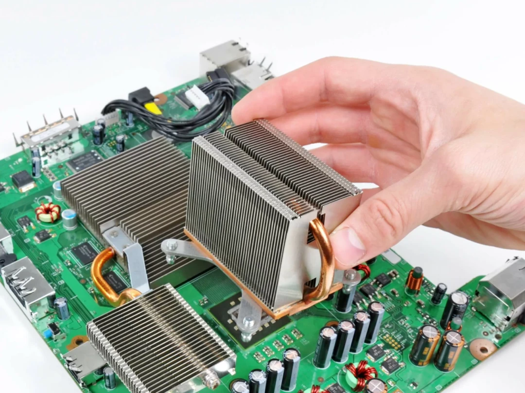
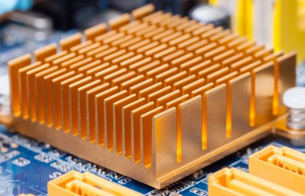
A heatsink may look simple, yet it quietly controls temperature in everything from CPUs to LED drivers. When heat builds up, performance drops fast. Understanding how a heat sink, thermal path, and cooling geometry work together keeps your system steady and safe.
Heatsink Materials: Aluminum, Copper, and Graphite
Material choice defines how a heatsink behaves under load. The base metal controls thermal properties, weight, cost, and machining flexibility. Below is a practical breakdown used in real heat sink design.
- Aluminium
- Key traits:
- Bon conductivity
- Lightweight structure
- Easy extrusion into fin shapes
- Common use:
- Electronique grand public
- LED dissipateur thermique housings
- Key traits:
- Copper
- Key traits:
- Plus élevé conductivity than Aluminium
- Dense and heavier
- Common use:
- High-power CPU heatsink heat sink bases
- Key traits:
- Graphite
- Key traits:
- Ultra-thin spreading
- Directional thermal properties
- Common use:
- Slim devices needing lateral heat spread
- Key traits:
Alloys blend materials science with manufacturability. Sheen Technology often combines Copper bases with Aluminium fins, balancing mass and performance in custom heat sink assemblies.
Exploring Fins, Microchannels, and Vapor Chambers
A dissipateur thermique is more than a metal block. Geometry drives transfert de chaleur l'efficacité.
- Fins
- Plate fins
- Simple geometry
- Stable airflow path
- Pin fins
- Better multi-directional cooling
- Higher turbulence
- Plate fins
- Microchannels
- Narrow liquid paths
- Increased surface interaction
- Vapor Chambers
- Flat sealed structures
- Phase-change cooling cycle:
- Liquid absorbs heat
- Vapor spreads energy
- Condenses and returns
When airflow is limited, Vapor Chambers improve spreading before convection even begins. Smart design and internal geometry prevent hot spots inside a dense heatsink module.
Thermal Conductivity and Surface Area Explained
Heat leaves a chip in stages: conduction, spreading, and then convection. Conductivité thermique defines how fast energy moves through solid materials. Larger Surface Area améliore dissipation de la chaleur into air, lowering température and overall résistance thermique.
| Type de matériau | Conductivité thermique (W/m-K) | Density (g/cm³) | Typical Heat Flux (W/cm²) | Relative Efficiency (%) |
|---|---|---|---|---|
| Aluminum 6063 | 200–215 | 2.70 | 5–15 | 75 |
| Copper C110 | 385–400 | 8.96 | 10–25 | 95 |
| Feuille de graphite | 150–1000 (in-plane) | 1.8–2.2 | 8–20 | 85 |
| Aluminum Alloy + Copper Base | 220–300 | 3.5–5.5 | 15–30 | 90 |
| Vapor Chamber Plate | 8000+ effective | — | 20–40 | 98 |
Plus élevé heat flux demands lower résistance thermique. A well-sized heatsink with optimized airflow keeps junction température within safe limits and boosts device l'efficacité.
Selecting Matériaux d'interface thermique for Optimal Contact
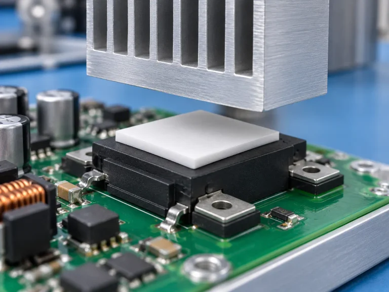
Even the best heatsink fails without proper contact. Microscopic gaps trap air, and air blocks heat flow. That’s where Matériaux d'interface thermique come in.
Communs TIMs include:
- Graisse thermique for thin bond lines
- Thermal pads for uneven surfaces
- Gap fillers for power modules
- Liquid metal for extreme performance
Application steps matter:
- Clean the chip and interface surface.
- Apply controlled TIM thickness.
- Mount the heat sink evenly.
- Verify mounting pressure.
In real builds, Sheen Technology engineers test mounting force and TIM spread patterns to reduce interface resistance. A properly installed heatsink with high-quality TIMs can drop core temperature by several degrees. That difference keeps CPUs, GPUs, and MOSFET systems running cool instead of cooking themselves.
3 Critical Factors in Heatsink Design
Un solide heatsink design isn’t just about adding metal and hoping for the best. It’s about smart material choices, sharp fin layout, and airflow control that actually works in real conditions. Let’s break it down in plain terms.
Material Selection and Thermal Conductivity
When designing a heatsink, Matériau choice directly impacts Conductivité thermique and overall Heat transfer.
- Metals dominate most designs because of their strong Propriétés in thermal performance.
- Cost, weight, and machinability also matter.
- Electrical isolation may push designers toward special Alloys or ceramics.
- Aluminium
- Good balance of cost and Conductivité thermique
- Lightweight
- Easy extrusion for complex heat sink shapes
- Copper
- Plus élevé Conductivité thermique
- Ideal for high-power ASIC or IGBT modules
- Heavier and more expensive
Thermal Conductivity Comparison
| Matériau | Conductivité thermique (W/m-K) | Density (g/cm³) | Relative Cost | Typical Use Case |
|---|---|---|---|---|
| Aluminum 6063 | 200–220 | 2.7 | Faible | LED heat sink |
| Copper C110 | 380–400 | 8.9 | Haut | High-power heatsink |
| Al Alloy 1050 | 190–210 | 2.7 | Faible | Extruded heat sink |
| Cu Alloy | 320–350 | 8.5 | Medium-High | Hybrid designs |
For advanced systems, like those built by Sheen Technology, the trick is pairing Matériau choice with realistic airflow and mounting conditions so the heatsink performs as expected, not just on paper.
Optimizing Fin Geometry for Maximum Surface Area
In any heatsink, Fin geometry controls how effectively Dissipation de la chaleur happens.
- Thin fins increase Surface area.
- Tighter Spacing boosts the area but raises resistance.
- Correct Épaisseur maintains structural stability.
- Surface Expansion
- Increase Surface area without choking airflow.
- Use skived fins for high aspect ratios.
- Efficiency Check
- Thin fins improve exposure.
- Excessively thin designs reduce Fin efficiency due to conduction limits.
- Shape Selection
- Straight fins: simple, cost-effective.
- Pin fins: better multidirectional Dissipation de la chaleur.
- Flared designs: guide airflow smoothly.
A smart heat sink layout balances Design intent with manufacturing limits. Extrusion works well for aluminum heat sink production. Skiving favors dense copper heatsink configurations where performance matters more than cost.
Balancing Airflow with Pressure Drop Constraints
A heatsink doesn’t work alone. Air has to move.
Key factors include:
- Airflow
- Pressure drop
- Fan capability
- System Resistance
Too much Pressure drop means the Fan struggles. Flow rate drops. Then Résistance thermique rises, and the cooling system loses its edge.
Here’s how to keep it practical:
- Match fin Spacing to the available Flow rate.
- Calculate total system Resistance, not just the heat sink.
- Confirm real-world Convection using thermal testing, not guesses.
In forced-air cooling, small design tweaks can shift junction temperature by several degrees. That’s huge for power electronics.
Sheen Technology approaches each heat sink project by aligning airflow modeling with physical prototyping, ensuring the final heatsink solution handles real Cooling demands without overloading the fan or wasting energy.
PCB Scenario: Heatsink Integration Tips
Smart PCB cooling is not rocket science, but small details make or break performance. A well-matched heatsink setup keeps chips calm, boosts lifespan, and saves late-night debugging headaches.
Matching Heatsink Bases to CPU and MOSFET Layout
When pairing a heatsink base avec un CPU ou MOSFET, alignment is everything. A sloppy fit kills heat flow fast.
- Core matching logic
- Component footprint
- Measure pad size precisely
- Compare against the base machining tolerance
- Layout spacing
- Check neighboring capacitors
- Confirm airflow path
- Mounting pattern
- Hole distance
- Screw diameter
- Component footprint
Thermal interface tuning matters too:
- Apply thin interface thermique material.
- Ensure base flatness within 0.05 mm.
- Confirm even pressure across the chip.
| Device Type | Typical Footprint (mm) | Recommended Base Thickness (mm) |
|---|---|---|
| CPU (Embedded) | 35 × 35 | 5-8 |
| MOSFET (TO-247) | 15 × 20 | 3-5 |
| Power IC (QFN) | 8 × 8 | 2–3 |
A clean dissipateur thermique contact zone means lower thermal resistance. That’s how a heatsink actually earns its keep.
Low-Profile Heat Sinks with Adhesive Tape Mounting
Compact boards call for a low-profile heatsink. No room for screws? Go with adhesive tape ou thermal tape.
- Ideal for:
- LED drivers
- Small power transistors
- Serré surface mounting dispositions
Key checks:
- Surface flatness
- Tape thermal rating
- Long-term bonding strength
In compact design work, a slim heatsink bonded well can outperform bulky hardware with poor contact. Keep the dissipateur thermique centered; edge overhang reduces effective dissipation de la chaleur.
Using Push Pins and Clips for Secure Attachment
Mechanical fastening gives stable pressure and better matériau d'interface thermique performance.
- Hardware hierarchy
- Push pins
- Quick install
- PCB-friendly
- Spring clips
- Constant load
- Good vibration control
- Screw systems
- Adjustable torque
- Best for heavier heatsink assemblies
- Push pins
Attachment checklist:
- Vérifier mounting hardware clearance.
- Apply the paste evenly.
- Tighten in a cross pattern.
Un solide retention mechanism keeps the heat sink locked down during transport and shock. That’s practical engineering, not overthinking.
Thermal Pad vs Gap Filler for Tight Spaces
Stack-up tolerance can be annoying. That’s where coussin thermique et bouche-trou choices matter.
- For tight spaces:
- Use a thin coussin thermique (0.5–1 mm).
- For uneven heights:
- Softer bouche-trou with higher compression rate.
Material comparison:
- Conductivité thermique above 3 W/m·K suits mid-power boards.
- High-viscosity interface material handles warped surfaces.
A well-chosen pad turns a basic heatsink into an efficient cooling device. Brands like Sheen Technology fine-tune pad hardness and aluminum flatness so each heatsink setup fits real PCB tolerances, not just lab drawings.
Get the spacing right, and your heat sink just works. No drama.
FAQs about Heatsink Heat Sink
Why are aluminum and copper dominant in heatsink applications?
Material choice shapes thermal conductivity, weight, and cost:
1. Aluminium
– Lightweight, corrosion-resistant, ideal for Extrusion and Die Casting;
– Balanced thermal conductivity for CPU and LED assemblies;
– Lower material cost for high-volume production.
2. Copper
– Higher thermal conductivity, suited for IGBT and ASIC modules;
– Often combined with Skiving or CNC Machining for dense fins;
– Heavier, but reduces junction temperature under heavy loads.
In some advanced builds, Graphite or Composite layers assist heat spreading, while Ceramic or Diamond inserts provide insulation in high-voltage designs.
How do fin structure and base design influence heat dissipation?
Heat dissipation is a balance between surface area and airflow control.
- Fins & Pins increase surface area; tighter spacing improves heat transfer but raises pressure drop.
- Base thickness affects heat spreading from MOSFET or Power Transistor packages.
- Heat Pipe or Vapor Chamber integration quickly distributes heat to outer fins.
- Microchannels or Cold Plate designs support liquid cooling where airflow is limited.
When airflow, pressure drop, and thermal resistance align, the heatsink performs with quiet intensity rather than brute force.
How do mounting hardware and thermal interface materials affect reliability?
Contact quality defines real-world performance.
Mounting Hardware Options
- Springs and Screws → stable pressure for GPU or CPU modules
- Clips and Push Pins → fast PCB assembly
- Adhesive Tape or Thermal Rivets → compact LED layouts
Matériaux d'interface thermique
| Matériau | Key Role | Typical Use |
|---|---|---|
| Graisse thermique | Fills micro-gaps | High-power CPU |
| Coussin thermique | Easy installation | LED boards |
| Phase Change Material | Softens under heat | ASIC modules |
| Graphite Pad | Thin heat spreading | Compact GPU |
| Liquid Metal | Ultra-low thermal resistance | Extreme cooling |
Without proper interface control, even the best Aluminum or Copper base cannot protect the junction temperature from rising. In cooling design, pressure and contact matter as much as metal.