-
الإضافة : المبنى 2، رقم 8 طريق هينغزوتانغ 8، دونغقوان
-
الهاتف : الهاتف +86 135 4224 3751

Thermal Management: Heat Dissipation for Photovoltaic Inverters
Heat dissipation for photovoltaic inverters isn’t some backstage detail; it’s the difference between smooth energy flow and a slow, expensive burnout. Push power density higher, and heat starts acting like an uninvited guest, creeping into every weak spot, shaving efficiency, stressing insulation, and quietly stacking up future failures.
The real play is materials—interfaces, substrates, coolants—each one either clearing a path for heat or bottling it up where damage begins.
Heat Dissipation for Photovoltaic Inverters: Key Points Serenade
→ Preserve Efficiency: Monitor ceramic substrate temperatures to avoid resistance rise and switching losses.
→ Material Matters: Choose low-resistance interfaces (thermal paste, liquid metal) and high-conductivity heatsink alloys.
→ Optimize Thermal Paths: Fill gaps with conductive pads, map DBC/IMS flow, and seal defects with epoxy or conformal coatings.
→ Cooling Strategy: Balance passive heatsinks with active liquid circuits for hotspot control and compact design.
→ Ventilation Best Practices: Design dedicated intake/exhaust vents and use adhesives to prevent air leaks.
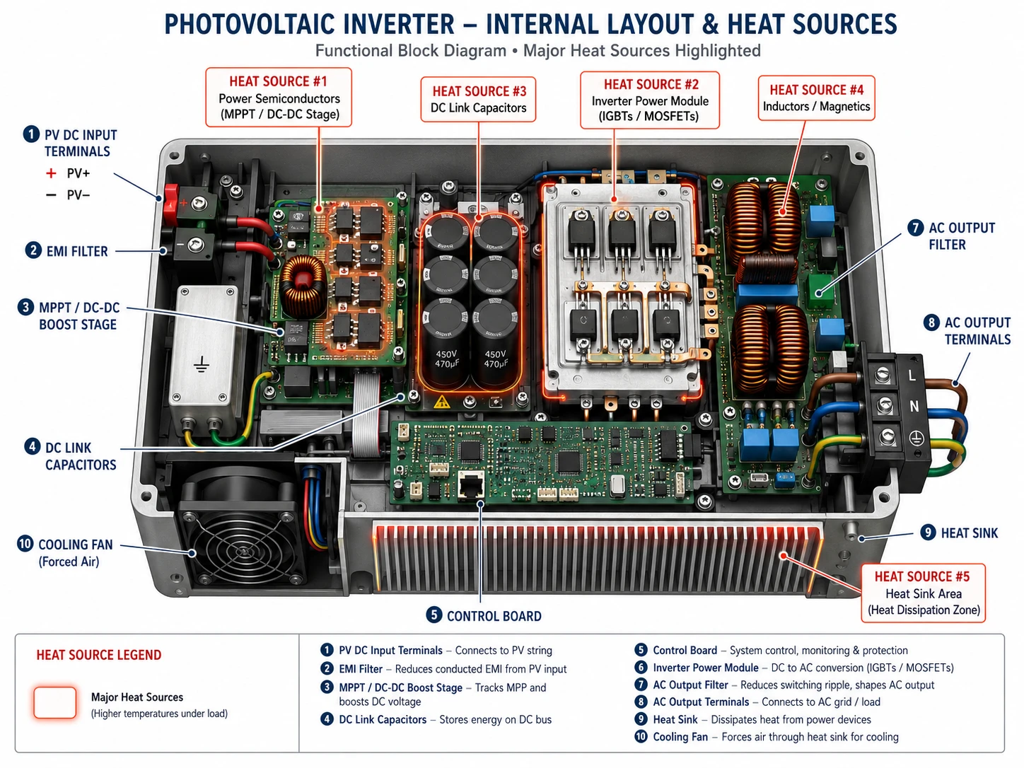
Why Is Heat Dissipation For Photovoltaic Inverters Crucial?
Heat dissipation for photovoltaic inverters isn’t just a technical checkbox; it keeps solar systems alive and kicking. When inverter cooling falls short, performance drops, parts age faster, and repair bills creep up. Good thermal management in solar inverters means steady output, safer operation, and longer service life.
The efficiency drop from hot ceramic substrate junctions
عندما ceramic substrate layers heat up, درجة حرارة الوصلة climbs. That’s where trouble starts for semiconductor devices handling Heat dissipation for photovoltaic inverters.
- Core impact on performance
- Rising heat generation increases internal resistance.
- Higher resistance → more power loss
- More power loss → lower inverter efficiency
- Lower efficiency → unstable solar inverter cooling
- Ongoing exposure leads to thermal degradation of DBC structures.
- Rising heat generation increases internal resistance.
- What this means in real operation
- Output power fluctuates during peak sun hours.
- Conversion rates slip below rated values.
- Long-term reliability takes a hit.
For Heat dissipation for photovoltaic inverters, even a small spike in junction heat can snowball. That’s why advanced substrate design from Sheen Materials focuses on lowering thermal resistance right at the source.
How thermal barrier coatings prevent insulation breakdown
A thermal barrier coating acts as a thin but tough protective layer between hot zones and sensitive مواد العزل.
- Under high thermal stress:
- The coating slows heat flow.
- Material integrity stays stable.
- مخاطر الانهيار العازل الكهربائي drops sharply.
- In layered inverter stacks:
- Ceramic base → coating shield → mica or polymer insulation
- يحافظ على electrical isolation
- Reduces micro-cracks
- Extends service intervals
- Ceramic base → coating shield → mica or polymer insulation
For Heat dissipation for photovoltaic inverters, keeping insulation cool isn’t optional. Once the breakdown starts, inverter heat management becomes a constant firefight instead of smooth operation.
Preventing thermal runaway with liquid metal interfaces
Thermal runaway is every engineer’s nightmare in Heat dissipation for photovoltaic inverters.
- Why hotspots escalate
- فقير مادة الواجهة الحرارية contact
- Uneven تبديد الحرارة
- ضعيف cooling system response
- How liquid metal helps
- Ultra-high التوصيل الحراري spreads heat fast.
- It fills microscopic gaps, cutting contact resistance.
- In some designs, phase change material behavior stabilizes peak loads.
The result? Lower junction peaks, stronger موثوقية الجهاز, and fewer surprise shutdowns. Heat dissipation for photovoltaic inverters becomes controlled, predictable, and built for the long haul.
Heat Dissipation For Photovoltaic Inverters: Material Choices
Heat dissipation for photovoltaic inverters is not just a design checkbox—it keeps solar power systems steady, safe, and long‑lasting. When photovoltaic inverter cooling is handled right, efficiency climbs and downtime drops. From interface layers to liquid cooling loops, smart material selection drives real heat transfer performance in solar inverter systems.
Thermal interface options: from thermal paste to phase change material
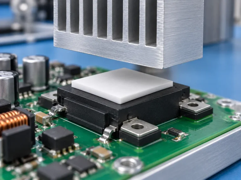
في heat dissipation for photovoltaic inverters, the مادة الواجهة الحرارية sits quietly between power modules and the heatsink, yet it can make or break نقل الحرارة الكفاءة.
- Interface foundations: 1.1 Surface mismatch control
- Microscopic voids increase interface resistance.
- A thin thermal paste fills air gaps and boosts التوصيل الحراري.
1.2 Gap management

*   **Gap filler** pads absorb tolerance stack-ups in large inverter assemblies.

*   Compressibility reduces mechanical stress during thermal cycling.
2. Advanced transition media: 2.1 Phase change material
- Solid at room temperature, softens near 50–60°C.
- Forms low-resistance contact under load.
2.2 Performance snapshot
| نوع المادة | الموصلية الحرارية (وات/م كلفن) | Typical Thickness (mm) |
|---|---|---|
| Thermal paste | 3–8 | 0.05–0.2 |
| Gap filler | 1-6 | 0.5–3.0 |
| PCM | 2–5 | 0.1–0.3 |
For photovoltaic inverter cooling, thinner and well‑compressed layers usually mean better solar inverter heat management.
Heatsink materials—aluminum alloy, copper, graphite, composite fin
متينة heatsink is the backbone of heat dissipation for photovoltaic inverters. Material choice shapes weight, cost, and thermal dissipation capacity.
- Aluminum alloy
- Light, corrosion‑resistant, easy for extruded heat sink design.
- Copper
- أعلى خواص المواد for conductivity; heavier but powerful.
- الجرافيت
- Excellent lateral spreading, great for hotspot control.
- Composite fin
- Hybrid base + fin stacks to enhance airflow paths.
According to the International Energy Agency’s 2025 solar update, power electronics thermal reliability is “a decisive factor in inverter lifetime across utility-scale PV plants.”
That’s why brands like مواد اللمعان tune fin geometry and base thickness together—air speed, fin pitch, and surface area all work as one system. In solar inverter cooling, airflow without smart material pairing is just hot air moving around.
Coolant fluids—deionized water, glycol mixture, heat transfer oil
Liquid loops raise the bar for heat dissipation for photovoltaic inverters, especially in high‑power string and central units.
- Coolant fluid selection logic1.1 Electrical safety
- Deionized water offers high heat exchange efficiency but needs conductivity monitoring.
- Heat transfer oil provides dielectric stability for sensitive layouts.
1.2 Environmental tolerance

*  "Glycol mixture" adds freeze protection in cold climates.
- Fluid properties comparison
- Thermal capacity
- اللزوجة
- Long‑term stability
- Application mapping3.1 Utility‑scale PV
- Liquid cooling + plate heat exchanger.
- Compact sealed loops.
In photovoltaic inverter thermal management, matching pump power with thermal fluid viscosity keeps energy use reasonable. مواد اللمعان supports fluid‑compatible channel plates designed to balance pressure drop and heat transfer for steady inverter cooling.
Potting & encapsulation—thermally conductive epoxy vs. silicone gel
Encapsulation locks in durability for heat dissipation for photovoltaic inverters.
- Potting compound purpose1.1 Moisture barrier1.2 Vibration damping1.3 Added thermal protection
- Material contrast: 2.1 Thermally conductive epoxy
- High strength
- مستقر قوة العزل الكهربائي
- Strong structural bonding
2.2  Silicone gel

*   Flexible

*   Relieves stress from thermal cycling

*   Easier rework
- Selection path for solar inverter heat control
- High mechanical load → epoxy.
- Frequent temperature swings → silicone gel.
In real photovoltaic inverter cooling projects, engineers often pair rigid encapsulation with compliant interface layers. That mix keeps نقل الحرارة efficient while shielding power modules from cracking. With tailored encapsulation systems from مواد اللمعان, solar inverter heat management stays reliable year after year.
5 Steps To Optimize Inverter Thermal Paths
Heat builds up fast in solar power electronics. If Heat dissipation for photovoltaic inverters is ignored, efficiency drops and parts age early. Smart thermal design keeps photovoltaic inverter cooling stable, safe, and cost‑effective—especially in high-density systems.
Step 1 – Map heat flow through DBC and IMS substrates
Getting Heat dissipation for photovoltaic inverters right starts deep inside the stack.
- Core conduction path:
- DBC substrates
- Ceramic layer → copper layer → solder joint
- Controls vertical التدفق الحراري
- IMS substrates
- Aluminum base → dielectric → copper trace
- Influences lateral نقل الحرارة
- DBC substrates
- Critical checkpoints:
- Measure junction-to-case resistance
- Run thermal mapping simulations
- Validate with infrared imaging
When reviewing substrate analysis, engineers typically evaluate:
- Hotspot density
- Copper thickness impact
- Ceramic conductivity
For power modules in solar inverters, tight التصميم الحراري reduces cycling stress and supports long-term photovoltaic inverter heat control.
Step 2 – Minimize gaps with thermal gap filler or conductive grease
Air gaps are silent troublemakers in Heat dissipation for photovoltaic inverters.
- Interface control:
- Uneven surfaces create thermal gaps
- Gaps raise contact resistance
- Poor contact slows التوصيل الحراري
- Optimization layers:
- Gap filler pads for thicker tolerances
- Conductive grease for thin precision bonding
- متقدم TIM (thermal interface material) for vibration zones
Performance factors to check:
- Compression rate
- مقاومة الضخ للخارج
- Aging stability
A stable واجهة حرارية keeps inverter cooling consistent across daily temperature swings. For utility-scale systems, this small detail makes a noticeable dent in overall solar inverter thermal management losses.
Step 3 – Integrate extruded profile heatsinks for maximum surface area
External cooling hardware often determines how well Heat dissipation for photovoltaic inverters performs under peak load.
- Heatsink structure:
- Base plate thickness
- Fin spacing
- Air channel direction
- شائع extruded heatsink advantages:
- عالية surface area
- Lightweight aluminum
- Cost-effective scaling
Typical comparison:
| Heatsink Type | Surface Area (cm²) | Thermal Resistance (°C/W) |
|---|---|---|
| Flat Plate | 450 | 1.8 |
| Standard Fins | 820 | 1.1 |
| Dense Fins | 1200 | 0.7 |
Lower resistance improves تبديد الحرارة and stabilizes junction temperatures. Advanced profile heatsinks paired with optimized airflow act like a passive heat exchanger, supporting long-duration photovoltaic inverter cooling in outdoor cabinets.
Step 4 – Circulate dielectric fluid or refrigerant for hot-spot control
When passive airflow isn’t enough, active cooling steps in.
- Liquid loop structure:
- Pump system
- Cold plate
- Circulation system
- Cooling media:
- Synthetic dielectric fluid
- Low-GWP refrigerant
- Engineered thermal fluid
Hot spots near switching devices respond well to direct-contact liquid cooling. Rapid heat transfer medium circulation evens out gradients and supports consistent Heat dissipation for photovoltaic inverters, especially in high-power string inverters above 150 kW.
This approach strengthens photovoltaic inverter heat control, where power density keeps rising year after year.
Step 5 – Seal with conformal coating or epoxy resin for long-term stability
Thermal work doesn’t end with cooling hardware. Environmental sealing matters.
- Protective layers:
- Acrylic conformal coating
- Silicone-based راتنجات الإيبوكسي
- Hybrid encapsulation compounds
- Protection targets:
- Moisture ingress
- Dust buildup
- Corrosion risk
الجودة sealing material يحسن استقرار طويل الأجل by protecting solder joints and preserving thermal paths. It also enhances moisture protection و corrosion resistance, which directly affect Heat dissipation for photovoltaic inverters in coastal or desert solar plants.
For manufacturers seeking reliable photovoltaic inverter cooling materials, مواد اللمعان supports integrated solutions—from substrate interface compounds to protective encapsulation. Smart material pairing keeps solar inverter thermal management steady, season after season.
Heat Sinks Vs. Liquid Cooling: Which Wins?
Heat dissipation for photovoltaic inverters is not just a technical checkbox; it decides system lifespan, uptime, and safety. When solar inverter heat dissipation falls short, efficiency drops fast. Let’s break down how passive and liquid approaches handle photovoltaic inverter cooling in real-world conditions.
Heat sinks
When discussing Heat dissipation for photovoltaic inverters, passive Fins and metal mass still carry serious weight in system design. For solar inverter heat dissipation, the classic aluminum or copper block is simple, steady, and trusted.
- Core heat path in photovoltaic inverter cooling
- Conduction
- Heat travels from semiconductor junctions into the المواد base.
- Copper lowers المقاومة الحرارية, aluminum reduces cost.
- Heat spreading
- كثيفة Fins increase Surface area.
- Geometry affects airflow channels.
- Heat release
- Natural or forced Convection transfers heat into the surrounding Airflow.
- Conduction
- Design considerations for Heat dissipation for photovoltaic inverters
- Material selection
- Copper: high conductivity, heavier load.
- Aluminum: lighter, easier machining.
- Thermal resistance chain
- Junction → case → sink → ambient.
- Installation factors
- Vertical airflow improves convection.
- Dust buildup reduces efficiency.
- Material selection
• Low maintenance
• No moving parts
• Lower upfront cost
For large-scale photovoltaic inverter cooling, passive sinks often require increased volume. That means bigger housings. Brands like Sheen Materials fine-tune extrusion density and surface finishing so solar inverter heat dissipation stays stable without crazy bulk. In moderate climates, passive Heat dissipation for photovoltaic inverters remains a practical, cost-conscious pick.
Liquid cooling
Liquid systems push Heat dissipation for photovoltaic inverters to another level. Instead of relying only on air, a Coolant circulates through a sealed Loop, guided by a Pump, absorbing heat at the Cold plate, then releasing it through a Heat exchanger أو Radiator.
Here’s how photovoltaic inverter cooling with liquid typically unfolds:
1) Heat enters the Cold plate through direct contact.
2) إن Coolant absorbs energy via controlled Fluid dynamics.
3) The heated fluid travels to a Radiator.
4) Heat disperses externally.
5) The cooled liquid cycles back.
Key advantages:
- Higher heat flux handling
- Compact layout
- Better hotspot control
Industry sentiment backs this trend:
BloombergNEF’s 2025 power electronics outlook notes that advanced cooling solutions are becoming standard in high-capacity renewable installations, driven by efficiency gains and tighter thermal limits.
That shift directly impacts Heat dissipation for photovoltaic inverters in utility-scale farms.
Still, added complexity matters. Pumps fail. Seals age. Maintenance plans must be real, not just promised. Sheen Materials supports system integrators with engineered Cold plate assemblies that balance reliability and performance.
In high-density solar inverter heat dissipation scenarios, liquid cooling clearly outperforms passive sinks. Yet for smaller systems, traditional photovoltaic inverter cooling through optimized heat sinks still holds ground. The winner? It depends on scale, budget, and how aggressively you need Heat dissipation for photovoltaic inverters to perform.
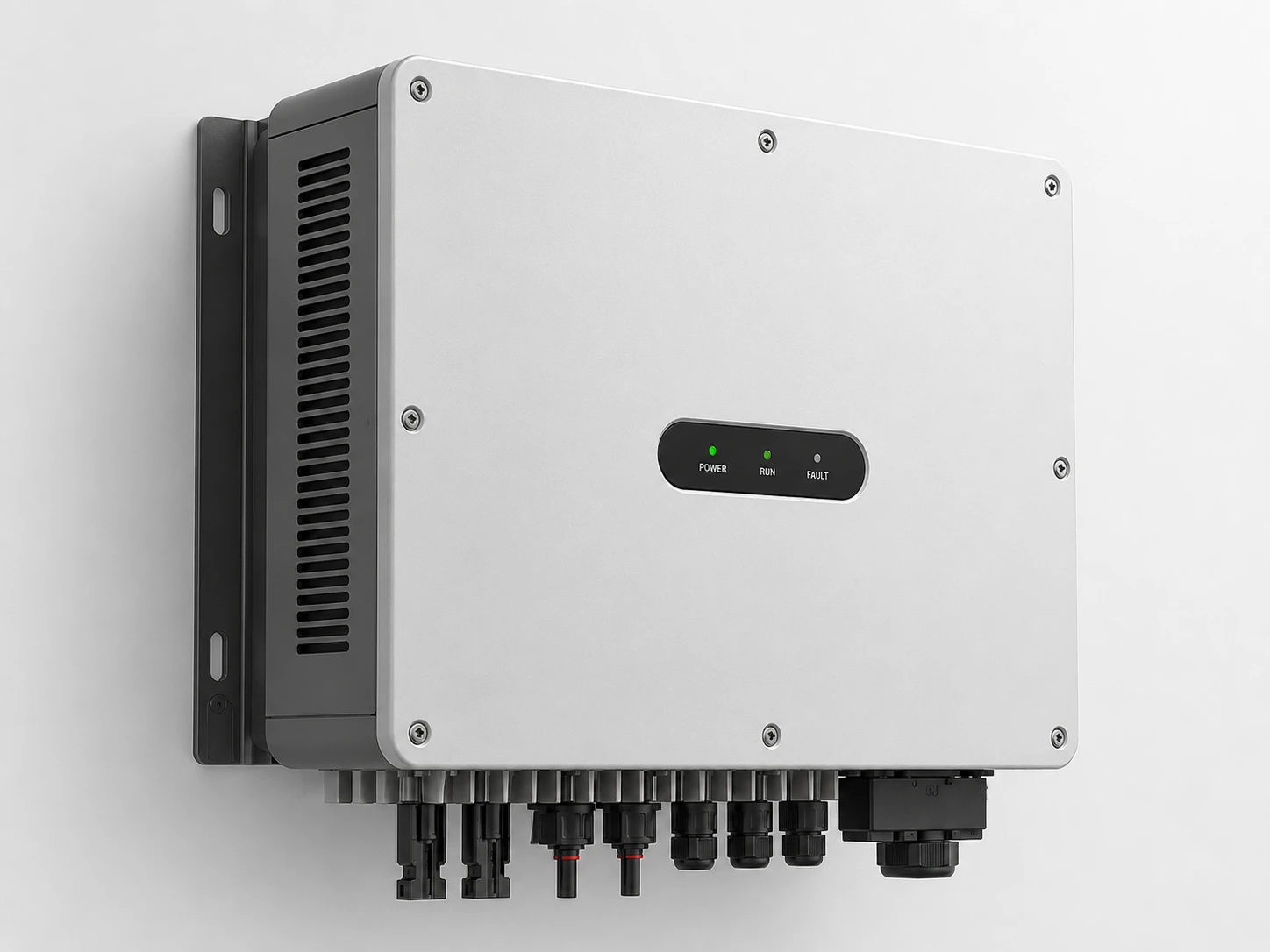
Inverter Installation: Ventilation Best Practices
Heat builds up fast inside power electronics. When we talk about Heat dissipation for photovoltaic inverters, we are really talking about airflow, insulation, layout, and sealing working together. Break the keyword down, and it’s clear: heat dissipation + photovoltaic + inverters. Good photovoltaic inverter cooling keeps output stable and extends hardware life. Poor ventilation? That’s when thermal management for solar inverters becomes a daily headache.
Strategic airflow layouts for forced-air convection
ذكي cooling system design starts with controlled airflow patterns. In forced convection setups, fan placement و vent layout decide how efficiently heat leaves the enclosure. For effective Heat dissipation for photovoltaic inverters, air must sweep across heatsinks, not skim past them.
Reference airflow performance data
| Fan Speed (RPM) | Airflow (CFM) | Internal Temp Drop (°C) | Noise (dB) |
|---|---|---|---|
| 1200 | 45 | 6 | 28 |
| 1800 | 68 | 11 | 34 |
| 2400 | 92 | 17 | 41 |
| 3000 | 115 | 22 | 48 |
For structured الإدارة الحرارية, follow this layout logic:
- Air Intake Zone
- Low-position cold air intake
- Dust filter layer
- Directed ducting toward power modules
- Heat Transfer Zone-
- Heatsinks aligned with the air circulation path
- Power modules spaced to avoid stagnation
* Temperature sensors near hottest MOSFET clusters
- Exhaust Zone-
- High-position hot air exhaust
- Short, straight discharge channel
- No cross-flow with intake
That’s real photovoltaic inverter ventilation strategy—simple airflow, no guesswork. Done right, Heat dissipation for photovoltaic inverters becomes predictable, not reactive.
Avoiding recirculation with proper intake and exhaust vents
Air recirculation quietly kills efficiency. Hot air looping back into the enclosure ruins air path optimization and weakens inverter heat control.
Keep intake and exhaust separated by distance and direction:
- Minimum 1.5× fan diameter spacing
- Opposite-side exhaust vent placement
- Shielded intake vent design
Now break it down further:
1) External Layout
- Intake facing shaded zone
- Exhaust facing an open ambient area
- No wall obstruction within 300 mm
2) Internal Flow Control
  - Baffles guiding flow in one direction

  - No open cavities that trap heat
- Clear route from **cold air intake to hot air exhaust.3) Performance Check
- Measure delta-T
- Inspect for hot spots
- Adjust fan curve
If exhaust air feels warm and intake air feels cool, you’re on track. If both feel warm, recirculation is happening. Fix it fast to maintain steady Heat dissipation for photovoltaic inverters.
Using thermal adhesive and electrical insulation tape to seal gaps
Tiny gaps mess with airflow and insulation. That’s where thermal adhesive, electrical insulation tape, and other sealing compounds step in.
Applications that support photovoltaic inverter cooling:
- Seal panel seams to prevent bypass airflow
- Reinforce cable entry points
- Close micro-gaps near heatsink bases
Layered sealing approach:
- Electrical Layer-
- قدم طلبك electrical isolation tape around live terminals
- Maintain creepage distance
- Thermal Control Layer-
- الاستخدام thermal adhesive between heatsink and casing where required
- Create controlled heat transfer barrier zones
- Environmental Layer-
- Add dust-resistant insulation materials
- Inspect for aging or peeling annually
Good sealing improves airflow discipline. Air goes where you want it, not where it sneaks through cracks. That’s how Heat dissipation for photovoltaic inverters stays consistent over years of operation, even under harsh rooftop conditions.