-
الإضافة : المبنى 2، رقم 8 طريق هينغزوتانغ 8، دونغقوان
-
الهاتف : الهاتف +86 135 4224 3751

Carbon Fiber Thermal Pads vs. Silicone: Optical Module Solutions
Heat is eating your optical modules alive, and the wrong interface pad quietly drives failures. Application Solution for Carbon Fiber Thermal Pads in Optical Modules cuts through that mess, pointing straight at performance risks buyers can’t ignore.
Silicone still fits uneven gaps, sure, but high-density transceivers demand cooler heads, tighter control, and fewer surprises when production really scales.
Reading Notes: Application Solution for Carbon Fiber Thermal Pads in Optical Modules
➔ Thermal Efficiency: Carbon fiber pads deliver superior thermal conductivity and low resistance, keeping laser diodes and ICs cool under heavy loads.
➔ Mechanical Reliability: Engineered compressibility and low CTE minimize stress in tight transceiver housings, ensuring long-term structural and signal integrity.
➔ Installation Best Practices: Die-cut for precise fit, clean mating surfaces, and apply uniform lamination pressure to eliminate air gaps and maximize heat transfer.
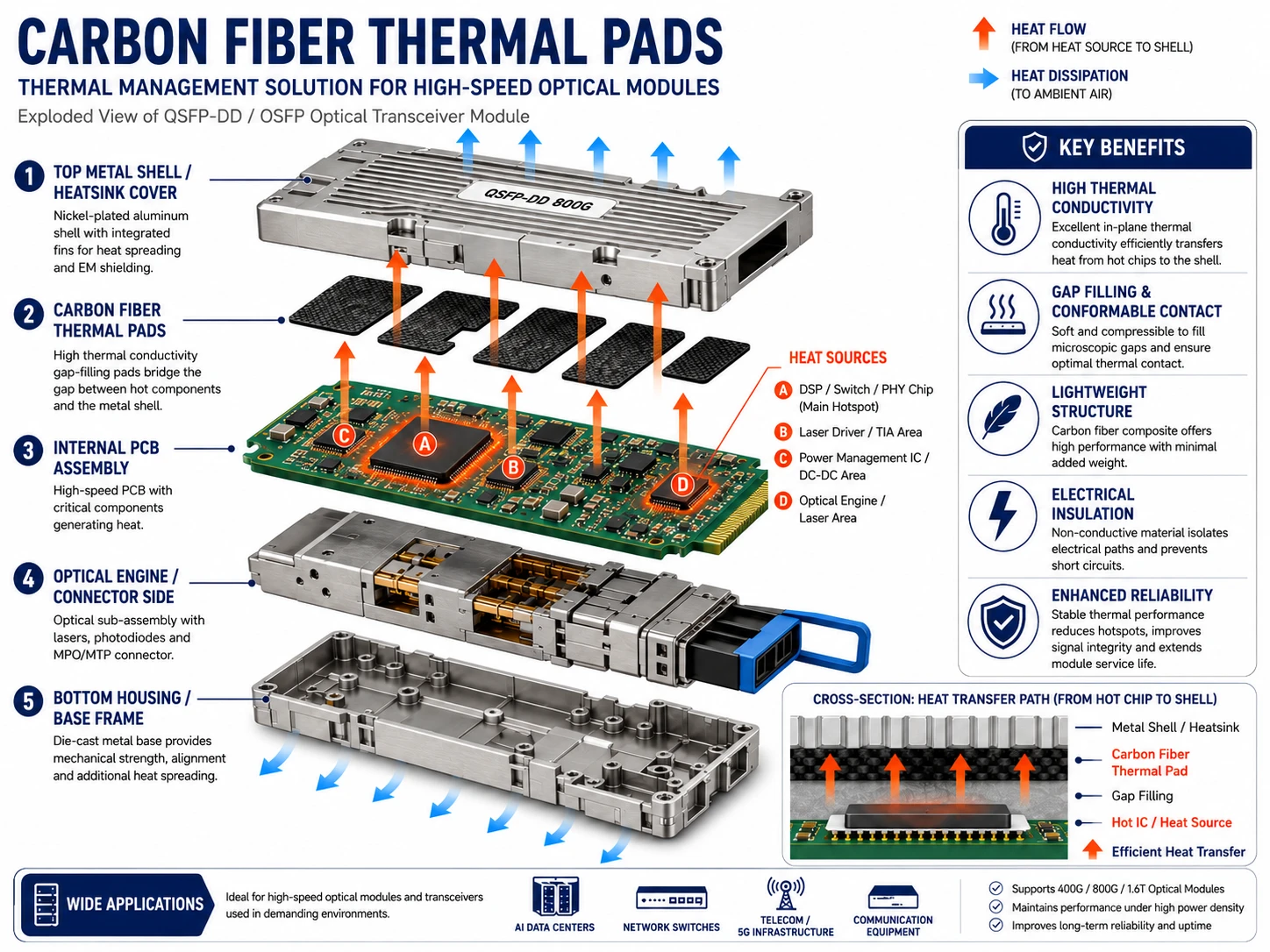
This image was generated using AI. Its content has been reviewed and approved by Sheen Materials; please feel free to save it.
Shocking Truth: Carbon Fiber Vs. Silicone Heat Transfer
A lot of engineers talk about heat like it’s abstract math. In optical hardware, it’s personal. A bad thermal choice cooks signal quality, shortens lifespan, and wrecks margins. Below, the contrast is practical, grounded, and street-smart, especially for teams hunting an Application Solution for Carbon Fiber Thermal Pads in Optical Modules that actually works in daily builds.
Carbon fiber thermal pad
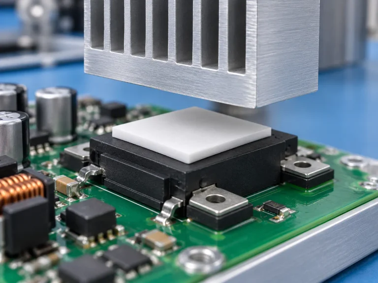
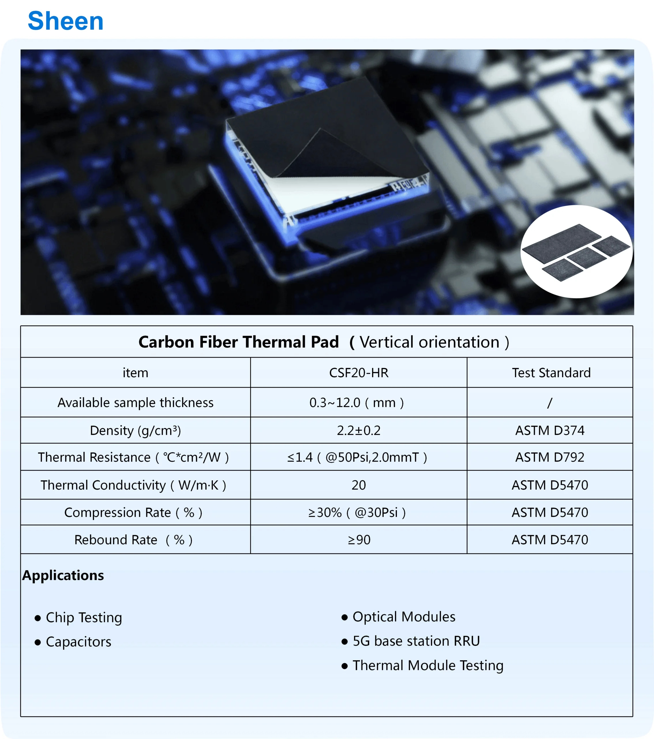
- Carbon fiber sits at the center of modern مادة الواجهة الحرارية design, prized for high التوصيل الحراري and fast تبديد الحرارة.
- Lightweight builds reduce mechanical stress on optical modules, which matters more than spec sheets admit.
- Durability holds under long laser duty cycles, with no sag and no creep.
- Heat moves laterally and vertically with low resistance.
- Structural stability stays intact under clamp pressure.
- Electrical isolation remains reliable around dense IC layouts.
Why engineers keep circling back: flexibility without softness, strength without bulk. In real application solutions for Carbon Fiber Thermal Pads in Optical Modules workflows, this balance saves rework hours.
Used correctly, the material flows like this:
- Source contact stays flat.
- Pad spreads heat fast.
- Housing releases it cleanly.
That’s why مواد اللمعان keeps pushing carbon-based options for high-power transceivers. It’s not hype; it’s repeatable performance. Many teams now treat Application Solution for Carbon Fiber Thermal Pads in Optical Modules as a baseline, not an upgrade. Even when layouts get tight, المرونة و lightweight design keep assembly sane. One more time, yes, the Application Solution for Carbon Fiber Thermal Pads in Optical Modules shows up because it earns that spot.
وسادة سيليكون
- سيليكون pads win on قابلية الانضغاط and easy سد الفجوة.
- Surface mismatch? المطابقة smooths it out.
- Built-in العزل الكهربائي keeps circuits calm.
• Softer feel, gentler clamp force, slower نقل الحرارة.
In practice, performance stacks like this:
1) Good contact on uneven housings.
2) Moderate التوصيل الحراري fits mid-power electronics.
3) Long-term stability depends on load cycles.
Short takes from the floor: softer pads install fast, rework is painless, and cost stays predictable. Still, once power density climbs, limits show up quickly. That’s why مواد اللمعان positions silicone as a support act, not the headliner. It complements, but rarely replaces, a carbon-driven Application Solution for Carbon Fiber Thermal Pads in Optical Modules when heat really starts to bite.
3 Key Benefits Of Carbon Fiber Thermal Pads
Carbon fiber thermal pads are showing up everywhere in optical hardware, and for good reason. This overview breaks down the Application Solution for Carbon Fiber Thermal Pads in Optical Modules, explaining why engineers keep reaching for this material when heat, space, and uptime all collide inside dense optical modules.
Enhanced thermal conductivity for laser diode cooling
Heat around a laser diode builds fast. The Application Solution for Carbon Fiber Thermal Pads in Optical Modules focuses on moving that heat out without drama.
- Core idea
- Carbon fiber structures boost التوصيل الحراري, speeding نقل الحرارة from the laser source into the واجهة حرارية and onward to the sink.
- How it plays out in real hardware
- Direct contact lowers junction temperature.
- Faster تبديد الحرارة stabilizes the optical module output.
- Cooler operation stretches component life.
- Typical performance snapshot
| Interface Material | الموصلية الحرارية (وات/م كلفن) | Operating Temp (°C) | Heat Transfer Efficiency (%) |
|---|---|---|---|
| Carbon fiber pad | 15-20 | 45 | 92 |
| وسادة سيليكون | 3-5 | 62 | 70 |
| Graphite sheet | 10–15 | 50 | 85 |
| Ceramic spacer | 2–4 | 68 | 65 |
This is why the Application Solution for Carbon Fiber Thermal Pads in Optical Modules keeps popping up in high-speed optics.
Improved compressibility in tight transceiver housing gaps
داخل transceiver housing, space is tight, and surfaces are rarely perfect.
- What matters most
- قابلية الانضغاط that fills tight gaps
- مستقر سد الفجوة without stressing the optical module
إن Application Solution for Carbon Fiber Thermal Pads in Optical Modules balances softness and strength. The pad conforms, yet stays mechanically calm. No cracked solder. No warped housings. Just steady contact across uneven interfaces using a reliable interface material made from carbon fiber.
Greater reliability under high power dissipation
عالية power dissipation tests every part of a thermal stack.
- Reliability drivers
- متناسق الإدارة الحرارية under rising heat load
- Material level: carbon fiber resists fatigue
- System level: steady الثبات الحراري
- Long-run effects
- Preserved long-term performance
- Fewer thermal cycles are hitting the optical module
- متناسق الإدارة الحرارية under rising heat load
In plain terms, this Application Solution for Carbon Fiber Thermal Pads in Optical Modules keeps working when power stays high, and downtime isn’t an option.
How To Choose Carbon Fiber Vs. Silicone Pads
Picking between carbon fiber and silicone pads can feel like a tiny parts decision, until the heat, fit, and safety rules start fighting each other. This breaks it down for optical hardware without the fluff, and keeps “Application Solution for Carbon Fiber Thermal Pads in Optical Modules” in view.
Evaluate thermal resistance against your operating temperature needs
If your optical module runs hot, the pad choice is basically your الإدارة الحرارية insurance. For an Application Solution for Carbon Fiber Thermal Pads in Optical Modules, start with the numbers that drive تبديد الحرارة and protect the die.
- Operating temperature reality check
- Map your worst-case temperature range (startup spikes, fan failure, blocked airflow).
- Tie that to your max junction/case limits; this is where المقاومة الحرارية makes or breaks stability.
- Material behavior under load
- Carbon-fiber-based pads can keep التوصيل الحراري steadier as pressure changes.
- Silicone can “settle” nicely, but some grades drift when continuously baked near the top of the spec.
| Pad type | Typical thickness (mm) | Through-plane thermal conductivity (W/m·K) | Approx. thermal resistance trend as thickness increases |
|---|---|---|---|
| Carbon fiber pad | 0.20 | 8–15 | Lower rise (flatter curve) |
| Carbon fiber pad | 0.50 | 8–15 | Moderate rise |
| Silicone gap pad | 0.50 | 3–8 | Noticeable rise |
| Silicone gap pad | 1.00 | 3–8 | Steeper rise |
For Sheen Materials customers doing an Application Solution for Carbon Fiber Thermal Pads in Optical Modules, the quick win is often thinning the interface while keeping compression in spec, so the المقاومة الحرارية stays tame.
Compare the mechanical stability and the coefficient of thermal expansion
This is where “looks fine on day one” can turn into connector stress three months later. Carbon fiber tends to hold shape; silicone tends to move, and that movement shows up as material stress after cycling.
- Start with خواص المواد that match your stack-up: substrate, lid, heatsink, cage.
- Compare the معامل التمدد الحراري (CTE) mismatch risk:
- Carbon fiber: lower expansion, better ثبات الأبعاد.
- Silicone: higher expansion; great compliance, but more pumping risk.
- Sanity-check الثبات الميكانيكي under clamp load:
- If you need repeatable contact pressure, carbon fiber often keeps السلامة الهيكلية cleaner.
- If your tolerances are messy, silicone’s squish can boost المتانة by reducing point loads.
Quick slang version: if the assembly is tight and picky, carbon fiber behaves; if the assembly is chunky and uneven, silicone forgives. Sheen Materials can help tune the pad hardness so your thermal pad choice doesn’t quietly bend the board.
Assess manufacturing methods: die cutting versus lamination
An “Application Solution for Carbon Fiber Thermal Pads in Optical Modules” isn’t just material; it’s also how the pad is made and placed. Manufacturing methods decide if your line operators love you or hate you.
- Die cutting fits when geometry is the boss
- Clean edges for cages, rails, and odd keep-outs.
- Better repeatability for pad formation when you’re packing parts tightly.
- Watch: tight radii can tear softer stocks, so test the production process early.
- التصفيح fits when the contact is the boss
- Improves interface wet-out and bonding; often better real-world contact for assembly techniques.
- Can integrate carriers/liners that speed handling and reduce fingerprints during material fabrication.
A practical combo shows up a lot: laminate for adhesion and handling, then die cut for shape. That mix is common in Sheen Materials builds for optical module thermal pad layouts, especially when “carbon fiber thermal pads” need crisp placement.
Balance dielectric strength with flammability rating requirements
Heat isn’t the only headline in racks; safety auditors show up, too. Your Application Solution for Carbon Fiber Thermal Pads in Optical Modules has to respect العزل الكهربائي and fire rules without compromising thermal performance.
- Safety requirements that bite in real installs
- تأكيد قوة العزل الكهربائي و جهد الانهيار at your actual thickness, not a marketing sample.
- Validate تصنيف القابلية للاشتعال (often UL 94 class expectations) for fire resistance in dense server airflow paths.
- Design choices that keep you out of trouble
- If carbon fiber content raises conductivity concerns, isolate with a proven insulating layer and re-check الخواص الكهربائية end-to-end.
- If silicone is used for compliance, pick a grade that meets سلامة المواد needs without going gummy at your درجة حرارة التشغيل.
Bottom line: pick the pad like you’re picking a system behavior, not a sheet of good. Sheen Materials can align carbon fiber thermal interface options with insulation targets so your optical module doesn’t pass thermal tests but fail compliance.
Step-By-Step: Installing Carbon Fiber Thermal Pads
Installing thermal interfaces inside optical modules can feel fussy, but it doesn’t have to be. This guide breaks down an Application Solution for Carbon Fiber Thermal Pads in Optical Modules, keeping things practical, hands-on, and friendly to real production floors.
Start with die cutting to fit the substrate and transceiver housing
Getting the shape right saves headaches later. During die cutting, the goal is a tight fit without stressing the substrate أو transceiver housing. Small mistakes here echo through the whole cutting process.
- Key checks that usually matter most
- Edge tolerance for component fitting
- Alignment with mounting points
- Clearance around connectors
A quick reference used by many teams working on an Application Solution for Carbon Fiber Thermal Pads in Optical Modules:
| المعلمة | Substrate Area (mm²) | Housing Clearance (mm) |
|---|---|---|
| Nominal design | 120 | 0.30 |
| Allowed minimum | 118 | 0.25 |
| Allowed maximum | 122 | 0.40 |
| Reject threshold | <116 | >0.50 |
Clean and prepare the integrated circuit and photodetector surfaces
Before anything sticks, clean و prepare the integrated circuit و photodetector surfaces. Dust, flux, and fingerprints quietly ruin thermal paths.
- What usually works best
- Solvent wipe for تحضير السطح
- Low-lint swabs during circuit cleaning
- Short drying time, no heat rush
This step supports any serious Application Solution for Carbon Fiber Thermal Pads in Optical Modules, especially when long-term stability matters.
Laminate the carbon fiber pad onto the laser diode assembly
Lamination is where feel meets control. The laminate action bonds the carbon fiber pad to the laser diode التجميع, and pressure balance is everything.
- Pad handling basics
- Avoid creasing the وسادة حرارية
- Center before contact
- Contact control
- Even force during pad lamination
- Watch edges during diode integration
Manufacturers often lean on suppliers like Sheen Materials here, since repeatable lamination is central to any Application Solution for Carbon Fiber Thermal Pads in Optical Modules.
Conduct final assembly testing for signal integrity and reliability
Once built, proof beats promises. Final assembly testing looks at heat flow, سلامة الإشارة, and long-haul الموثوقية.
- Typical validation flow
- Electrical sweep for integrity check
- Thermal cycling under load
- Stress screening for performance validation
This closing loop ensures the Application Solution for Carbon Fiber Thermal Pads in Optical Modules holds up in real optical networks, not just on paper.
Application Solution For Carbon Fiber Thermal Pads In Optical Modules Overview
Application, Solution, Carbon, Fiber, Thermal, Pads, Optical, Modules—those words sound stiff, but the pain is simple: hot parts throttle and optics get flaky. This Application Solution for Carbon Fiber Thermal Pads in Optical Modules ties practical الإدارة الحرارية to real hardware constraints. Expect clear choices, fewer guessy builds, and carbon fiber thermal pad options from Sheen Materials that fit tight spaces.
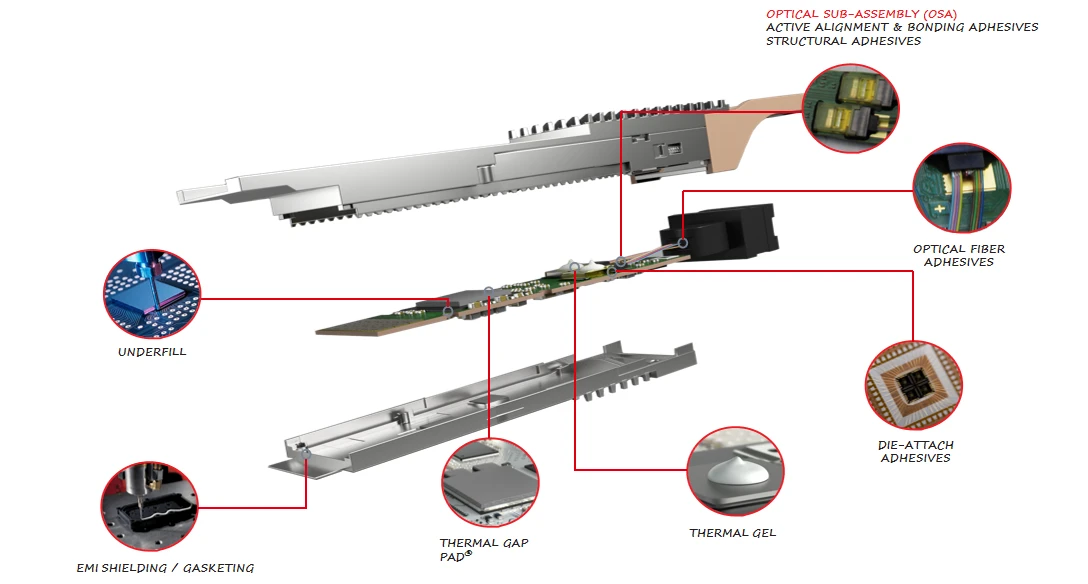
Data center QSFP-DD module cooling strategy
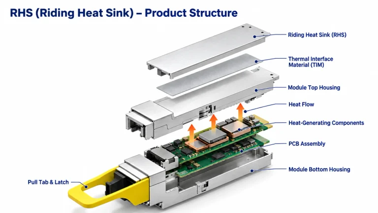
بالنسبة ل data center QSFP-DD module, the cooling budget is tiny, and the heat source is not. An Application Solution for Carbon Fiber Thermal Pads in Optical Modules works when the carbon fiber thermal pads create a clean path from the hot transceiver silicon into the cage.
- Core heat path (keep it boring and direct):
- Contact stack
- Die-to-lid interface (often already set)
- Lid-to-pad interface (where pad compressibility matters)
- Pad-to-cage interface (where flatness and clamp force decide the win)
- Target outcome
- Lower interface loss, so تبديد الحرارة stays steady during bursts
- Contact stack
- Placement rules that don’t bite later:
- Cover the highest تبديد الحرارة zones, not the whole lid.
- Avoid overlapping vents or EMI springs; “more pad” can mean “less airflow.”
- Verify compression in the assembled module, not on the bench.
- Build note: Sheen Materials carbon fiber pad SKUs are commonly picked here because thin formats are still usable in-plane spread, which is handy in a high-density transceiver layout.
OSFP module integration for high-speed interconnects
OSFP runs hotter in real life because high-speed lanes and tighter faceplate packing don’t care about your lab assumptions. This Application Solution for Carbon Fiber Thermal Pads in Optical Modules aims to keep the optical module stable while the data rate swings up and down all day.
Quick-fit checks for integration مع interconnects:
- List-style sanity list:
- The pad doesn’t push the PCB into the connector misalignment.
- Pad area matches the actual hot IC footprint (not the shield can outline).
- The pad surface isn’t shedding fibers or dust into the optical cavity.
A short, practical sequence:
- Map hot spots under worst-case data rate traffic.
- Pick a pad thickness to hit the clamp force without bowing the cage.
- Tune the pad shape so it dumps heat into metal, not into air gaps.
- Re-test signal quality; “cooler” is pointless if the interconnects get stressed.
Symbol-style callout:
- * If you’re mixing materials, keep electrical isolation in mind; carbon systems can vary, so spec it clearly with Sheen Materials before locking the BOM.
Thermal management in fiber optic communication connectors
في fiber optic connector used for communication, the goal is quiet reliability: no cooked parts, no drifting alignment, no weird intermittent faults. A clean Application Solution for Carbon Fiber Thermal Pads in Optical Modules treats the connector as a heat bridge with strict mechanical boundaries.
- Where the heat actually goes (nested view):
- interface constraints
- Limited z-height
- Repeated mate/unmate wear
- Heat path options
- Pad to metal shell (preferred when the shell is a real sink)
- Pad to chassis rail (works when the rack side has mass)
- Risk controls
- Keep نقل الحرارة consistent so the optical signal doesn’t wander
- Maintain insulation targets while improving الإدارة الحرارية
- interface constraints
Multiple short notes, because that’s how connectors work:
Tight tolerances matter. Pads must not creep into the ferrule zone. Sheen Materials can supply die-cut shapes so the pad stays out of the “no-touch” areas while still moving heat.
Server rack substrate design for optimal power dissipation
At rack level, this turns into server rack substrate design: spread heat, dodge hot spots, and help every المشتت الحراري breathe. The Application Solution for Carbon Fiber Thermal Pads in Optical Modules scales up nicely when pads couple modules to the rack’s metalwork, improving power dissipation without turning assembly into a wrestling match.
- System layout choices (multi-level):
- Rack conduction network
- Module cage → rail → substrate plate
- Plate → chassis wall → facility airflow
- Electronics constraints
- Keep serviceability: pads should survive pull cycles
- Avoid shorting risks around electronics; specify insulation clearly
- Cooling behavior
- Use pads for spreading, not as a replacement for cooling airflow
- Rack conduction network
| Location in rack | Typical pad thickness (mm) | Expected contact pressure (kPa) |
|---|---|---|
| QSFP-DD cage to rail | 0.3 | 80 |
| OSFP heat frame to midplate | 0.5 | 120 |
| Connector shell to chassis bracket | 0.2 | 60 |
Natural wrap-up, keeping it real: if your rack metal is thin or floating, pads can’t perform magic. When the metal path is solid, Sheen Materials’ carbon fiber pad builds usually make the thermal story simpler, and this Application Solution for Carbon Fiber Thermal Pads in Optical Modules becomes repeatable instead of “it worked once.”