-
АДД: Здание 2, № 8 Хэнчжутан Роуд, Дунгуань
-
Телефон: +86 135 4224 3751

How to Select Thermal Silicone Pad Hardness for Different Applications
For thermally conductive silicone pads, “softer is not necessarily better.” Key factors include the pressure you can apply during installation, the flatness of the contact surfaces (or the size of the gap tolerance), and whether the material will collapse or lose its shape over time. Below, I outline practical hardness ranges based on specific application scenarios and highlight common pitfalls to avoid.
“Thermal Silicone Pad Hardness can make or break a volume assembly: too hard risks poor contact and component stress; too soft can complicate handling and stability.
SheenMaterials engineers specify Shore A hardness separately from thermal conductivity, since formulation, thickness, compression, and interface conditions govern heat transfer.
From CPUs to automotive ECUs, the smart buy balances fit, dielectric performance, compliance, process needs, and lot consistency. This guide shows how.
Quick Insights on Thermal Silicone Pad Hardness
- Soft vs. Hard: Shore A 30–50 pads excel in gap filling under low clamp force; Shore A 70–90 pads resist deformation and oil bleed.
- Independent Metrics: Evaluate hardness separately from thermal conductivity—formulation, thickness, and filler loading dictate heat flow.
- Application Fit: Match pad Shore A to assembly needs—LEDs favor low A, CPUs medium-hard, power modules soft high-κ.
- Quality Assurance: Verify with ASTM D5470 thermal impedance tests and ASTM D2240 durometer checks; ensure RoHS/IATF compliance and controlled storage.
Thermal Pad Hardness Classifications Explained
Thermal Silicone Pad Hardness affects how a pad compresses, handles, and maintains contact between hot electronics and a heat sink. In practical terms, softer material squeezes into gaps more easily, while harder material keeps its shape. Picking the right silicone hardness is a pretty straightforward way to control pressure, fit, and long-term cooling behavior.
Soft Pads (Shore A 30–50): Maximizing Compressibility
- A softer Силиконовая накладка favors Сжимаемость и Соответствие.
- Under light pressure, it provides effective Gap filling around uneven components.
- Better contact can support Теплопроводность by reducing insulating air pockets.
- Gentle compression also relieves stress on fragile parts.
- Under light pressure, it provides effective Gap filling around uneven components.
For Thermal Silicone Pad Hardness selection, Shore A 30–50 is a handy choice when surfaces vary in height.
Medium Pads (Shore A 50–70): Balancing Density and Conductivity
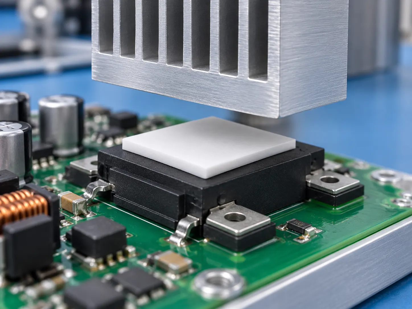
Средний Твердость brings enough Плотность to hold shape without making the pad excessively stiff. That balance can keep the Interface consistent during assembly.
A good fit matters, too. Controlled compression supports Mechanical stability, while suitable material thickness and conductivity help limit Термическое сопротивление. In Electronics, this middle range often provides predictable Thermal performance where both cooling and physical support count.
Hard Pads (Shore A 70–90): High Tensile Strength & Low Oil Bleed
- Higher hardness improves Handling during Assembly.
- Greater Прочность на разрыв helps resist stretching.
- Лучше Puncture resistance can protect the pad during installation.
- Firm construction supports long-term Долговечность.
- Reduced deformation can improve Reliability.
- Нижний Oil bleed is generally easier to achieve with firmer formulations.
Thermal Silicone Pad Hardness in the 70–90 range suits applications where mechanical strength matters nearly as much as thermal contact.
3 Factors Impacting Pad Hardness Selection
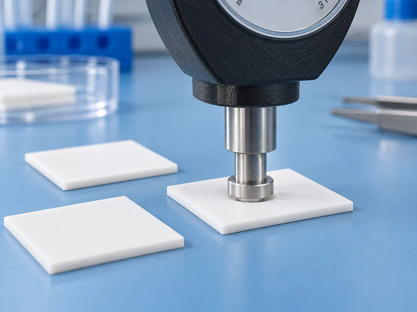
Choosing Thermal Silicone Pad Hardness is a balancing act: heat flow, compression, and fit all matter. A pad that looks good on paper can still miss the mark in hardware, so SheenMaterials evaluates thermal silicone choices against real assembly conditions.
Thermal Conductivity vs. Shore A Hardness
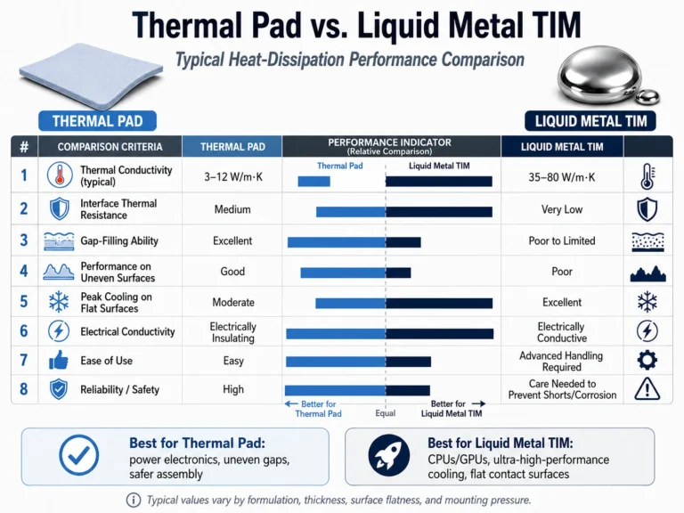
Thermal Silicone Pad Hardness does not directly predict теплопроводность. Filler content and silicone chemistry can change heat performance without producing the same firmness.
- Свойства материала
- Filler loading can raise conductivity while also changing material rigidity.
- Сайт elastomer matrix influences flexibility and contact behavior.
- Thermal checks
- ASTM D5470 testing helps verify the heat transfer coefficient and resulting термическое сопротивление rather than relying on Shore ratings alone.
That keeps Thermal Silicone Pad Hardness and heat-transfer performance from getting mixed up.
Compressibility Requirements under Clamping Force
For assemblies with limited clamping force, softer pads generally conform with less pressure. Harder thermal silicone may need extra force to reach useful contact.
- Check mechanical demands.
- Measure the required deflection percentage.
- Account for surface unevenness and available контактное давление.
- Check long-term behavior.
- Excessive mechanical deformation can load components or circuit boards.
- Stress relaxation may reduce contact over time.
The right Thermal Silicone Pad Hardness supports useful сжимаемость without squeezing the assembly too hard.
Thickness Tolerance and Application Scenario Fit
Thickness changes both fit and thermal resistance, so thickness tolerance needs to match the real application scenario.
- Fit
- Compare component height с assembly tolerance.
- Allow enough заполнение зазоров to maintain interface contact.
- Processing
- Die cutting and stamping favor stable dimensions.
- Manual placement or surface lamination may benefit from easier handling and controlled pad deformation.
In short, Thermal Silicone Pad Hardness should be chosen alongside thickness, geometry, and installation method—not as a stand-alone number.
How Hard Should Your Thermal Silicone Pad Be?
Thermal Silicone Pad Hardness affects how well a pad fills gaps without losing shape. In practice, choosing silicone hardness means balancing compression, pressure, thickness, and heat flow—areas where SheenMaterials helps match pads to real hardware needs.
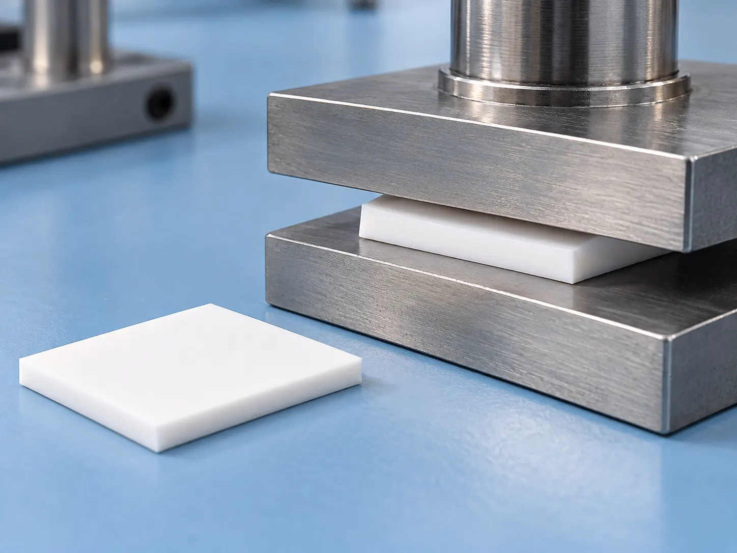
First, standardize the hardness units.
There are three common ways to specify thermal silicone pads—don’t mix them up when comparing:
- Shore 00 / Asker C: Most commonly used for soft foam or ultra-soft thermal pads, particularly in the 0.5–3mm thickness range and low-pressure applications.
- Shore A: Used for relatively firm, solid, or highly filled pads; a “low” numerical value does not necessarily indicate softness, and direct conversion across different scales is not possible.
- Shore C: Used by some manufacturers for medium-soft thermal pads; while similar to Shore A, it is not the same scale. When requesting a quote, ask the manufacturer to provide a stress-strain curve (stress vs. compression rate).
From an engineering perspective, it is more reliable to directly provide the compressive stress-strain curve and the thermal resistance at a specified pressure; this is more useful than looking at hardness alone.
Selecting Hardness Based on Application (Typical Ranges)
Low voltage, fragile components, plastic housing/thin PCB
- Typical applications: Heat spreading in smartphones/tablets, small sensors, optical modules, fragile chips, and snap-fit structures requiring low engagement force.
- Compression rates of 20–30% are permissible; the soft pad conforms to microscopic surface irregularities to reduce contact thermal resistance without damaging components.
- Recommended: Shore 00 hardness of approx. 10–30, or Asker C 10–20 (ultra-soft grade).
- Note: Excessive softness can lead to stretching, wrinkling, or misalignment during assembly; fiberglass reinforcement is recommended for ultra-thin pads (<0.8 mm).
General Consumer Electronics / Power Supplies / LED / Notebooks
- Typical applications: Power adapters, LED aluminum-based PCBs, laptop CPU/GPU heat spreaders, routers, and small industrial control modules.
- Recommended hardness: Shore 00 30–50 (or approximately Shore A 10–30 if the manufacturer uses the Shore A scale).
- Compression rate: 15–25%. Thermal conductivity: 1.5–4 W/m·K (consumer electronics) or 3–6 W/m·K (industrial/medium-power applications), depending on power requirements.
- This category represents the “most cost-effective” general-purpose segment; the material can fill uneven surfaces without squeezing out excessively under pressure.
Uneven surfaces/components of varying heights, large gap tolerances
- Typical scenarios: Uneven heights of capacitors, inductors, or chips on the PCB; rough machined surfaces on heat sinks; custom metal housings.
- Recommendations: Ultra-soft materials (Shore 00 20–40 or Asker C 10–30). For high thermal conductivity requirements, soft filler formulations are also suitable (e.g., Shin-Etsu TC-CA series: low hardness/high conductivity, 1.8–5.2 W/m·K, Asker C 10–40).
- Guiding principles: The rougher the surface, the greater the height variation, and the lower the clamping force, the softer the material should be; however, ensure sufficient thickness and keep the compression rate below 30%.
Servers/CPUs/ASICs/high-power modules: flat-surface mounting with screw locking.
Typical examples: server CPU heat spreaders, GPUs, FPGAs, communication base station PAs, and IGBT/SiC power modules.
Recommend:
- Low-to-medium pressure applications: Shore 00 50–70, 10–20% compression.
- High clamping force, controlled bond line thickness (BLT) required: Harder—Shore A 50–70 or Shore 00 70+, 5–15% compression.
Don’t blindly chase the “softest” material for high-power applications: while soft, low-pressure pads excel at filling gaps, excessive screw pressure can cause them to squeeze out or lead to uncontrolled thickness; conversely, hard pads offer more stable thermal resistance through flat contact, but insufficient pressure can result in poor thermal coupling.
For IGBT and automotive-grade applications, thermal conductivity typically starts at 5–8 W/m·K; for insulation-critical scenarios, key requirements include a dielectric breakdown voltage of ≥10 kV/mm, UL94 V-0 flammability rating, and low compression set.
Automotive Electronics / Energy Storage / Vibration Environment
- Typical applications: OBCs, motor drives, BMS, domain controllers, battery modules, and outdoor industrial controls.
- Recommended specifications: Primarily medium-to-high hardness (Shore 00 60–70 or medium Shore A); harder grades are suitable for applications involving vibration or high clamping forces.
- Performance requirements are far more critical than hardness alone: temperature resistance of −40°C to 150°C (or higher), low compression set, fiberglass reinforcement for creep resistance, low oil bleed, halogen-free/RoHS compliance, and UL94 V-0 rating.
- Soft pads applied with low pressure are suitable for large battery surfaces with low heat flux density; however, avoid using materials that are too soft for structural support points between cells or modules, as they may collapse over time.
Automated Production Line / Ultra-thin Cutting
Supports any thermal conductivity level, though fiberglass reinforcement and slightly higher hardness (Shore 00 60+ or medium-firm Shore A) are preferred; features dimensional stability, secure nozzle adhesion, and no stringing. While ultra-soft pads are manageable for manual application, they tend to wrinkle during automated application.
For thicknesses of 0.76 mm or less, a fiberglass carrier is strongly recommended; otherwise, the material is prone to tearing.
Rules for Matching Compression Ratio with Thickness
Target compression: 10–30% (most manufacturers specify thermal resistance based on 15–30% compression); 20–30% for low-pressure sensitive components, and 10–20% for high-pressure power components.
Thickness selection formula: Nominal pad thickness ≈ actual maximum gap + (10–30%) × nominal thickness; common rule of thumb: select 1.0 mm for a 0.8 mm gap, or 0.6–0.8 mm for a 0.5 mm gap.
Consequences of over-compression: Permanent deformation, oil bleeding, poor resilience, and a subsequent increase in thermal resistance.
Pressure estimation: Soft pads can function at 10–30 psi, whereas hard pads require 30–80 psi to achieve rated performance; calculate required screw torque or spring force by multiplying the contact area by the target pressure.