-
АДД: Здание 2, № 8 Хэнчжутан Роуд, Дунгуань
-
Телефон: +86 135 4224 3751

What Changes in Thermal Design When GPU Power Exceeds 1000W?
With a Thermal Interface Material Solution
Over the past decade, GPU performance has continued to rise. But for thermal management engineers, the real pressure has not come only from higher computing power. It has come from higher power consumption.
A few years ago, a high-performance GPU was still around 300W. Then the industry entered the 500W era. After that, GPU power pushed beyond 700W.
Now, driven by the explosive demand for AI large model training, the industry is moving toward the era of 1000W-class GPUs.
Many people focus on the obvious excitement:
- Higher specifications
- Stronger computing power
- Faster model training
But for thermal engineers, the more urgent question is brutally practical:
How do you actually remove 1000W of heat from a GPU?
Because once GPU power breaks through the 1000W level, the traditional logic of thermal design is being completely rewritten.
What Does It Mean When GPUs Enter the “Kilowatt Era”?
Many people do not have an intuitive feeling for what 1000W really means.
Let’s look at it another way.
The heat generated by one GPU is roughly equivalent to:
- 10 electric heaters rated at 100W running at the same time
Or:
- A small induction cooker is heating continuously
But here is the real problem: this heat is not evenly distributed.
It is concentrated in a chip area that may be only the size of a palm, or even smaller.
That means one thing:
Heat flux density per unit area is rising sharply.
In the past, thermal management systems mainly faced the challenge of increased total heat load.
Now, they face a far tougher challenge:
Exploding heat flux density.
These are not the same level of difficulty.
The Evolution of GPU Thermal Design
Air Cooling Is Approaching Its Limit
For a long time, the most common cooling solution in the server industry was air cooling:
Fans + heat sinks.
This approach is simple, mature, and relatively low-cost.
But as GPU power continues to climb, air cooling is running into its natural bottleneck. The reason is straightforward: air has limited specific heat capacity, and its ability to carry heat away is far weaker than that of a liquid.
When GPUs enter the 1000W era, simply increasing airflow creates new problems:
- Noise rises sharply
- Energy consumption continues to increase
- Data center PUE becomes worse
- Cooling improvement becomes increasingly limited
In recent years, many data centers have started to realize one hard truth:
Adding more fans is no longer enough.
That is why liquid cooling is accelerating rapidly.
Cold Plate Liquid Cooling Is Becoming the Mainstream Solution
The most important upgrade path for today’s AI servers is:
Cold plate liquid cooling.
In simple terms, coolant flows through a cold plate placed close to the GPU. Heat is transferred from the GPU to the cold plate, then into the liquid, and finally removed through the circulation system.
Compared with air cooling, liquid cooling offers clear advantages:
- Higher cooling capacity
- Lower noise
- Lower energy consumption
- Higher rack-level power density
As a result, more and more AI server manufacturers are fully deploying liquid cooling architectures.
For future GPUs above 1000W, liquid cooling is no longer just an optional upgrade.
It is becoming a necessity.
HBM Is Becoming a New Hotspot Area
In the past, many engineers focused mainly on the GPU core.
But in the AI era, HBM, or high-bandwidth memory, is becoming a new thermal management challenge.
The reason is simple:
- HBM sits extremely close to the GPU
- Data exchange is frequent
- Power consumption continues to rise
- Temperature sensitivity is very high
In many cases, the GPU core temperature may still appear normal, while the HBM is already approaching its temperature limit.
Therefore, modern thermal design is no longer just about cooling a single chip.
It has evolved into coordinated thermal management for:
GPU + HBM.
This places much higher demands on both cold plate design and TIM materials.
Thermal Design Targets Are Changing
In the past, many people believed that TIM materials were only auxiliary materials.
Whether they were changed or not seemed to make only a small difference.
But after GPU power exceeded 1000W, engineers began to realize something critical:
The real bottleneck in cooling efficiency is often not the cold plate, but the interface thermal resistance.
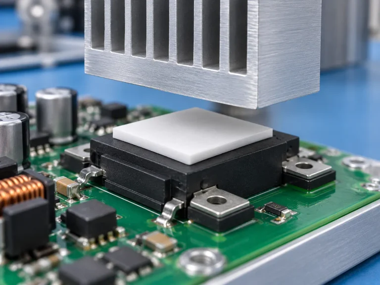
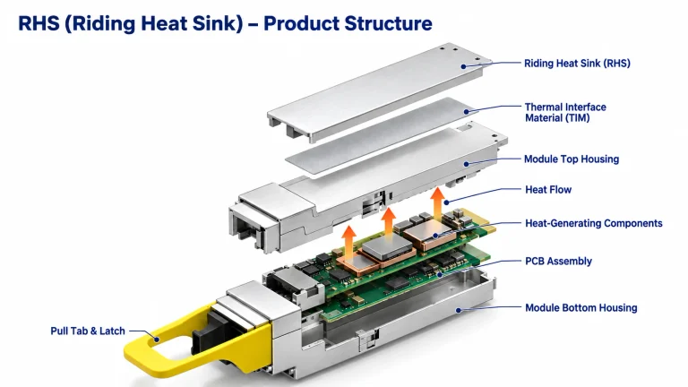
Heat must pass through the thermal interface material, or TIM, before it can move from the GPU to the cold plate.
If interface thermal resistance is not well controlled, even the strongest liquid cooling system cannot transfer heat away fast enough.
That is why, in recent years, thermally conductive TIM materials have become a major focus in AI server R&D.
The industry focus is also shifting:
From:
Теплопроводность
To:
Overall thermal resistance
In the past, the goal of server thermal design was simple:
- Do not crash
- Do not trigger alarms
- Do not exceed temperature limits
Today, AI servers are focused on much more demanding targets:
- Maximum computing performance release
- Long-term stable operation
- Higher energy utilization efficiency
As a result, thermal management has moved from being a basic functional guarantee to becoming a key factor that directly affects business value.
Whoever can reduce GPU temperature by a few degrees may gain:
- Higher operating frequency
- Higher computing output
- Lower energy consumption
The explosion of AI servers is driving the upgrade of the entire thermal management industry.
From cold plate liquid cooling, thermal gel, thermal grease, EMI shielding materials, phase change materials, to complete system-level thermal design, the thermal supply chain is growing rapidly.
Thermal management material companies represented by Материалы для отделки have continued to expand in the AI server thermal management field in recent years.
Around products such as:
- Boron nitride thermal pads
- Graphene thermal pads
- Carbon fiber thermal pads
- Thermal gels
- Термическая смазка
- Thermal silicone pads
- EMI materials
Sheen Materials provides thermal management solutions for GPU servers, HBM cooling, liquid cooling systems, and related high-power applications.
1000W Is Only the Beginning
Many people think a 1000W GPU is already extreme.
But judging from the development speed of the AI industry, 1000W is very likely only a new starting point.
In the coming years, the industry will continue moving toward:
- Larger models
- Higher computing power
- Denser computing clusters
All of these will push power consumption even higher.
And every additional 100W of power means a significant increase in thermal management difficulty.
Therefore, future competition in AI servers may look like a competition between chips on the surface.
But in reality, it will increasingly become a competition in thermal management capability.
Because the real limit of computing power is not determined only by the GPU itself.
It is also determined by whether the heat can be removed fast enough.
Can Sheen Materials Provide a Thermal Solution for GPUs Above 1000W?
For GPU applications with power consumption exceeding 1000W, Sheen Materials has designed a sandwich-style layered thermal solution.
This solution matches the strengths of three different thermal materials with the thermal conduction and insulation requirements of different GPU regions, forming a highly efficient thermal management system that works as an integrated structure.
Solution Architecture Overview
Core area, between the GPU chip and the cooling cold plate, TIM1: Используйте GSF90-03 graphene thermal pad to maximize core heat transfer capability.
Expansion area, between the cold plate and the heat sink, TIM2: Используйте CSF45 carbon fiber thermal pad to maintain low thermal resistance while improving cost-effectiveness.
High-voltage area, including MOSFETs, driver ICs, and other power modules: Используйте BSF series boron nitride thermal pads to provide reliable electrical insulation.
Detailed Layered Thermal Solution
1. Core Area, TIM1: Graphene Thermal Pad
This area is responsible for high-heat-flux conduction from the GPU core to the active cooling device, such as a vapor chamber, also known as VC.
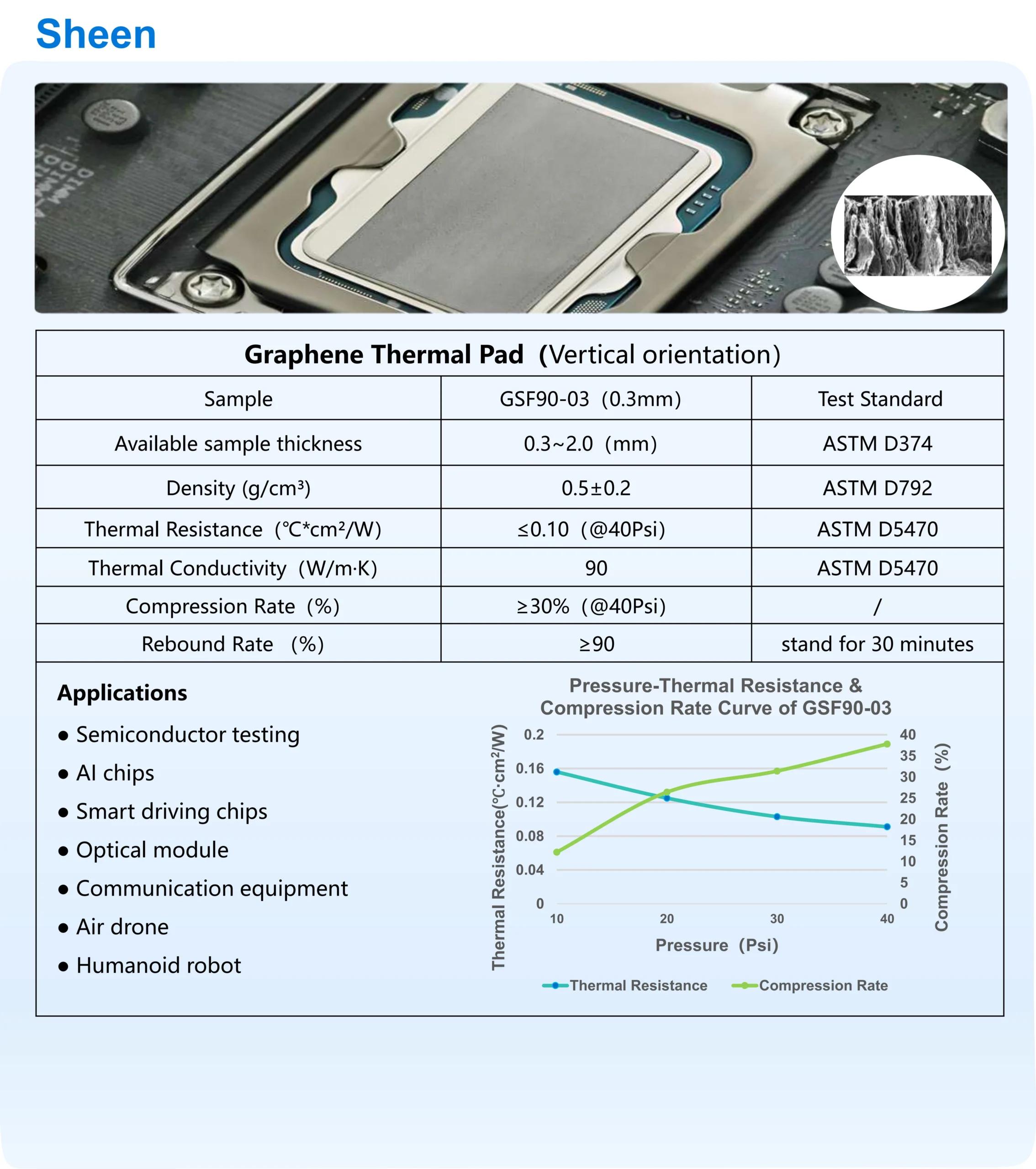
Recommended model: GSF90-03 graphene thermal pad
Key performance:
- Thermal conductivity: ≥90 W/m·K. This is far higher than traditional interface materials, ensuring rapid heat transfer.
- Thermal resistance: ≤0.013°C·in²/W at 40 psi. Extremely low thermal resistance helps minimize obstacles in the heat transfer path.
- Thickness: 0.27–0.33 mm. The thin specification helps reduce the length of the thermal conduction path and maximize heat transfer efficiency.
- Recovery rate: ≥55%. This allows the material to closely conform to the chip and heat sink surfaces, reducing contact thermal resistance.
- Operating temperature: -40°C to 150°C. Suitable for long-term use in demanding environments such as data centers.
2. Expansion Area, TIM2: Carbon Fiber Thermal Pad
This area is located inside the thermal module, between the vapor chamber and the fan heat pipe heat sink.
At this stage, the heat flux density has been significantly reduced. The requirement for thermal conductivity is slightly lower than in the GPU core area, but cost-effectiveness and interface filling become more important.
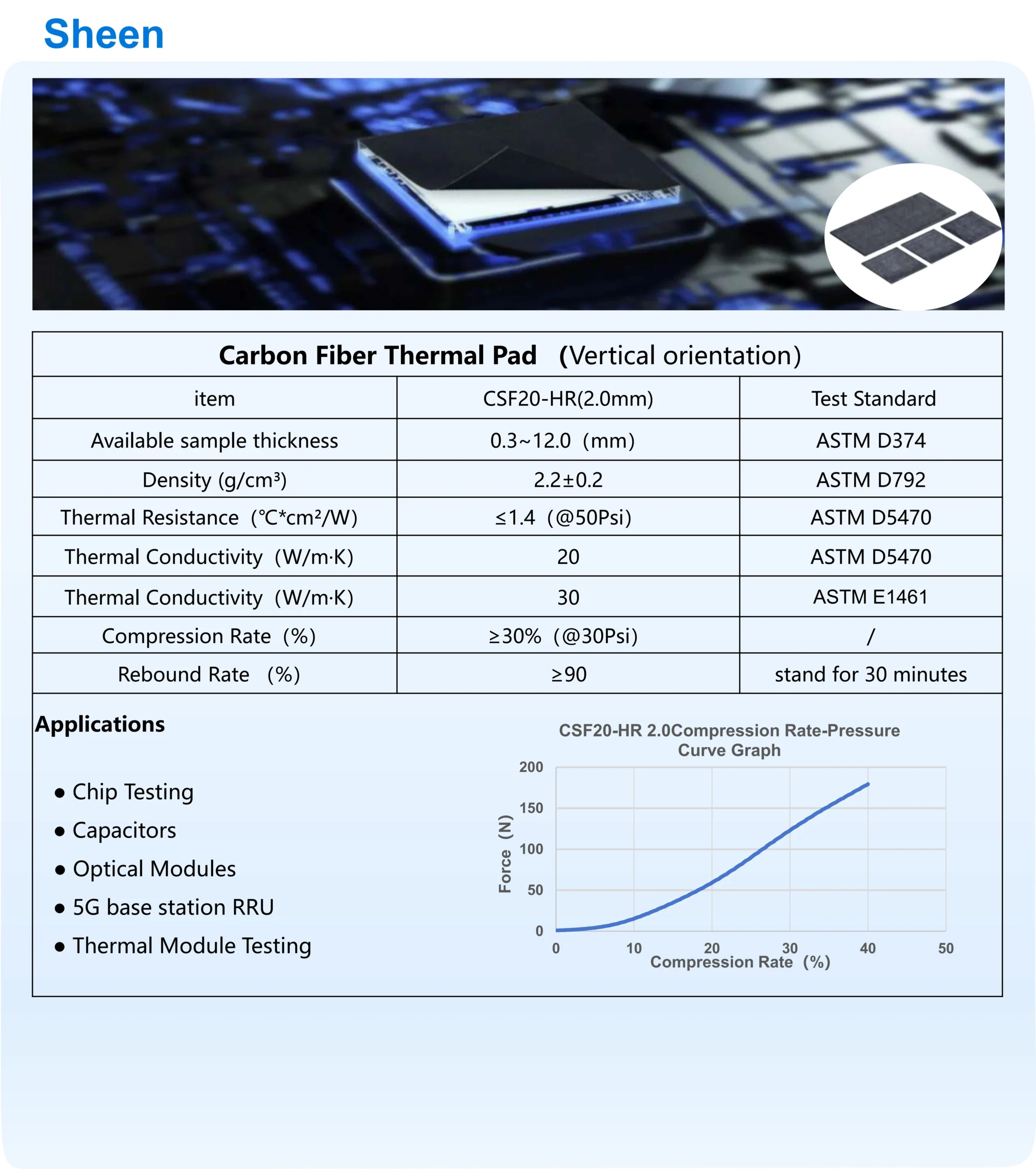
Recommended model: CSF20-HR carbon fiber thermal pad
Key performance:
- Thermal conductivity: 30.0 W/m·K. This is still a high-performance thermal material, far better than ordinary silicone pads, while also offering cost advantages.
- Thermal resistance:< 1.4(@50Psi). This enables efficient transfer of heat coming from the TIM1 layer.
- Flexibility: Built with a liquid silicone rubber base material, it offers excellent softness and compressibility, allowing it to adapt to larger assembly tolerances.
- Application: Widely used in high heat dissipation products such as chips and graphics card memory. Its performance and durability have been validated across multiple application fields.
3. Peripheral and High-Voltage Areas: Boron Nitride Thermal Pad
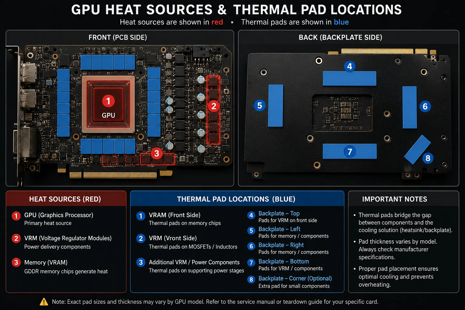
Around the GPU core, there are usually densely arranged power components such as MOSFETs, inductors, and capacitors.
These areas require thermal conduction to support heat dissipation, but they also demand strict electrical insulation.
For high-voltage and high-heat-flux areas such as VRM modules, reliable electrical isolation is absolutely critical.
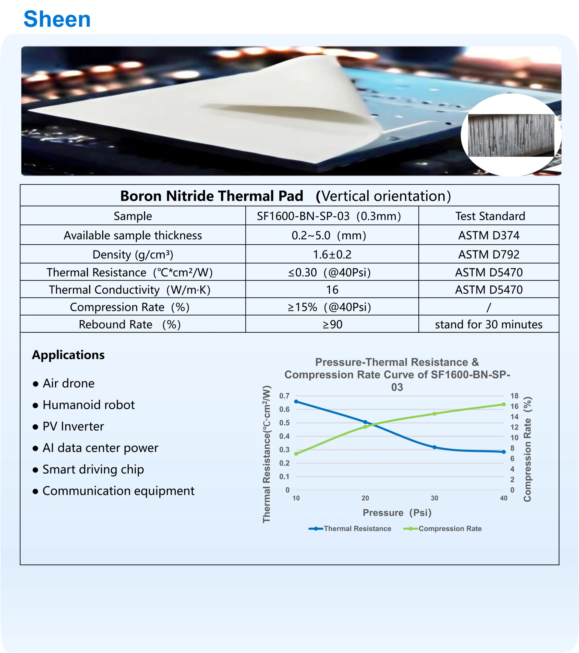
Recommended model: BSF series boron nitride thermal pad
Key performance:
- Electrical insulation: Volume resistivity ≥10¹³ Ω·cm, dielectric strength ≥8 kV, providing a strong electrical safety margin. The volume resistivity of boron nitride thermal pads can reach 10¹⁴–10¹⁶ Ω·cm, further strengthening their high-insulation performance in high-power electronic devices.
- Thermal performance: Thermal conductivity ≥15 W/m·K, providing high heat transfer efficiency and playing a key role in maintaining the stability of MOSFETs, inductors, and other components.
- Thermal resistance: ≤0.10°C·in²/W at 40 psi for 0.7 mm thickness, enabling a smooth thermal conduction path.
- Application: With both thermal conductivity and electrical insulation, this material is widely used in communication equipment, power equipment, and other products with high heat dissipation requirements.
Solution Summary and Selection Recommendations
This solution provides a precise thermal conduction path for GPUs above 1000W. The core logic is as follows.
Ultra-High Heat Flux Area: Chip Core
Use a graphene thermal pad with extremely high thermal conductivity and good flexibility to rapidly “pull” heat away from the chip.
This selection is based on the anisotropic structure of graphene, which can form an efficient thermal conduction network and deliver excellent through-thickness thermal performance.
Its core value is to build an ultra-low-thermal-resistance high-speed highway for heat transfer.
Medium-to-High Heat Flux Area: Thermal Interface Zone
Use a carbon fiber thermal pad that combines high thermal conductivity with cost-effectiveness to guide heat outward.
The excellent thermal conductivity of carbon fiber, combined with the flexibility provided by the liquid silicone rubber base, gives the material strong tolerance for assembly variation.
Its core value is to balance efficient thermal conduction with assembly convenience.
High-Voltage Sensitive Area: Peripheral Power Supply Zone
Use a boron nitride thermal pad that provides both thermal conductivity and high electrical insulation to ensure electrical safety.
Hexagonal boron nitride, or h-BN, is an excellent insulating filler. This allows the pad to deliver both:
- High thermal conductivity through filler-based thermal pathways
- High electrical insulation through the polymer matrix
Its core value is to solve the conflict between heat transfer and insulation in high-voltage environments.
In summary, through this layered solution, Sheen Materials’ GSF90-03, CSF45, и BSF series products work together to address the core challenges of 1000W-class GPU cooling:
- High-heat-flux conduction in the GPU core
- Assembly adaptability
- High-voltage electrical safety
Together, they provide reliable heat transfer support for the entire cooling system.
For samples of GSF90-03, CSF45, и BSF series products, please contact our sales engineers:
[email protected] [email protected]
Recommended Articles
BSF1600 Boron Nitride Thermal Pad: Test Report and Application Cases
5 Essential Testing Methods for Carbon Fiber Thermal Pads
Why Carbon Fiber Thermal Pad Dedicated for 5G Base Stations Wins
Carbon Fiber vs Graphene Thermal Conductivity Comparison: The Guide
How to Choose: A Comprehensive Carbon Fiber Thermal Pad Selection Guide
Engineering High-Density AI Server Cooling with Boron Nitride